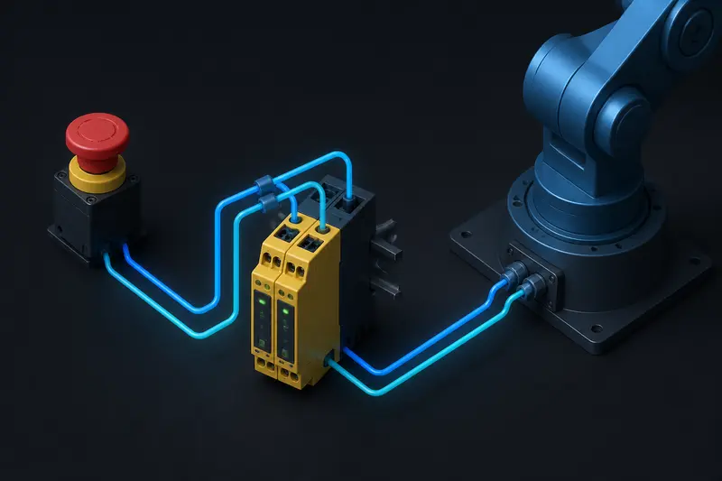
Most hobbyist and small industrial robot arms ship with a single wire running from a push button to a driver's enable pin. That wire is not an e-stop circuit design that meets Category 3 requirements, it is a single point of failure. If the wire breaks, if the button's contact welds shut, or if the driver's enable pin fails high, the arm keeps moving when someone hits the button. This article walks through building an actual dual-channel Category 3 e-stop circuit for a robot arm, with real part numbers, a cross-fault detection check, and a worked stop-response time budget.
What Category 3 Actually Requires
Category 3, as defined in ISO 13849-1, requires two things that a single push button and a single wire cannot provide:
- Redundancy. A single fault (broken wire, stuck contact, shorted output) must not by itself cause loss of the safety function. This means two independent signal channels, not one.
- Fault detection. The system must detect when the two channels disagree (cross-fault) and stop rather than continuing to trust whichever channel still reports safe.
In practice this means the e-stop push button has two normally-closed (NC) contacts, wired as two separate loops, both feeding a dedicated safety relay rather than a general-purpose I/O pin on your motor controller.
The Circuit: Button, Safety Relay, Driver Enable
A minimal Category 3 e-stop loop for a small robot arm looks like this:
- A dual-channel e-stop push button (for example a Schneider XB4 or IDEC HW-series mushroom head with two NC contacts, channel A and channel B).
- Both channels wired into a safety relay module rated for Category 3/4 (for example a Pilz PNOZ or an IDEC HR6S). These relays run internal cross-fault detection: they compare channel A and channel B on every cycle and latch a fault if they disagree for longer than a few milliseconds.
- The safety relay's two independent output contacts (OSSD or dry contacts, depending on model) wired into the enable/STO (Safe Torque Off) pins of your motor driver, not into a GPIO pin read by your microcontroller's firmware.
The critical design decision is step 3. If the driver has a hardware STO input, use it. STO physically disconnects gate drive to the motor's power stage, so even a firmware crash or a runaway control loop cannot keep the motor powered. If your driver has no STO input, wire the safety relay output in series with the main power contactor feeding the driver instead of relying on a software-read enable pin.
A common mistake is wiring the e-stop button's two channels in series into a single GPIO pin, then reading that pin in firmware and calling motor.disable(). This is a Category B design at best: a single firmware hang, a stuck interrupt, or a shorted pin defeats the entire safety function.
Worked Cross-Fault Detection Example
Say your safety relay's datasheet specifies a maximum discrepancy time of 3 ms between channels before it declares a fault. Consider a failure where channel A's wire chafes against the arm's base and shorts to 24V while channel B remains correctly wired.
- Before the short: both channels read closed (0V drop, current flowing, contacts intact). Relay sees agreement, output stays enabled.
- At the short: channel A now reads permanently closed regardless of button state, channel B still tracks the button correctly.
- When the button is pressed: channel B opens immediately, channel A stays shorted closed. The relay sees the two channels disagree for longer than its 3 ms discrepancy window.
- Result: the relay latches a fault and drops both output channels, disabling the driver, even though channel A alone would have kept reporting "safe".
This is the entire point of the redundant wiring: the single-fault (the chafed wire) does not silently disable the safety function, it gets caught and converted into a safe stop.
Sizing the Stop-Response Time Budget
Category 3 also implies a performance requirement: the arm must actually stop before it can do harm. Budget the total stop time as three stacked delays:
- Button and relay reaction time, typically 10-20 ms for a mechanical e-stop button plus a hardware safety relay (check the relay datasheet's own response time, separate from its discrepancy window).
- Driver STO turn-off time, typically under 5 ms once STO is asserted, since it is a hardware gate-drive cutoff, not a software ramp-down.
- Mechanical coast-down time, which depends on the joint's inertia and any braking. For an unbraked joint this is the dominant term.
Take a shoulder joint spinning at a worst-case 90 deg/s (about 1.57 rad/s) with a reflected inertia at the motor shaft that gives it roughly 150 ms to coast to zero once torque is removed (measured empirically by cutting power and timing the joint with a stopwatch or encoder log). The total stop time is:
t_stop = t_button+relay + t_STO + t_coast
t_stop = 15 ms + 5 ms + 150 ms = 170 ms
In that 170 ms, the joint sweeps roughly 1.57 rad/s x 0.170 s = 0.267 rad, about 15.3 degrees, before it is fully stopped. If your safety distance calculation (per ISO 13855, using an approach speed of 1.6 m/s for a human hand) requires the arm to be stopped before an operator's hand can cross a given guard distance, this 170 ms number, not the marketing spec of the safety relay alone, is what you plug into that calculation. If 15 degrees of travel is unacceptable near a pinch point, add a mechanical brake on that joint to cut the coast-down term, since it is almost always the largest contributor.
Common Wiring Mistakes
- Wiring both channels through the same connector or the same cable jacket. A single crush or cut event can then take out both channels at once, defeating redundancy. Route channel A and channel B through physically separate cable paths where possible.
- Daisy-chaining the e-stop in series with unrelated safety devices (light curtains, door switches) without separate relay inputs. This makes it impossible to tell which device tripped, which slows diagnosis and tempts people to bypass the whole chain during debugging.
- Relying on the motor driver's software fault flag as the only feedback that the e-stop worked. Add a physical indicator (the safety relay's own status LED, or a dry contact feeding a separate indicator light) so a bypassed or miswired e-stop is visually obvious before someone reaches into the workspace.
None of this replaces a full risk assessment for your specific arm and application, but the pattern above, dual-channel button into a dedicated safety relay into a hardware STO or main contactor, with a measured stop-time budget, is the concrete baseline that turns "we have an e-stop" into something that actually satisfies Category 3.
Building or studying robotics?
Arcbotix publishes practical guides on robotics engineering, control systems and real-world builds. Explore more articles on the blog.