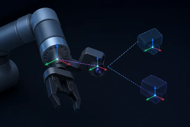
Hand-Eye Calibration for a Robot Arm Camera: A Worked Numeric Example
A worked eye-in-hand calibration example: real pose-pair transforms, the AX=XB setup, and why a single robot motion can never solve it.
Read more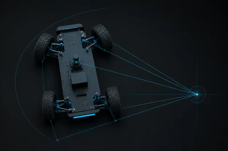
Ackermann Steering Kinematics for Robots: A Worked Example
A worked example of Ackermann steering kinematics: computing the turning radius, the separate inner and outer front wheel steering angles, and why a single steering angle applied to both wheels causes tire scrub.
Read more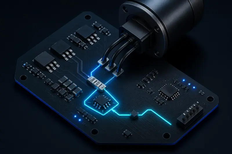
Current Sensing Circuit Design for Robot Motor Drivers: A Worked Shunt Resistor Sizing Example
A worked numeric example of shunt resistor current sensing for a robot motor driver, from shunt value and power dissipation through amplifier gain and ADC resolution.
Read more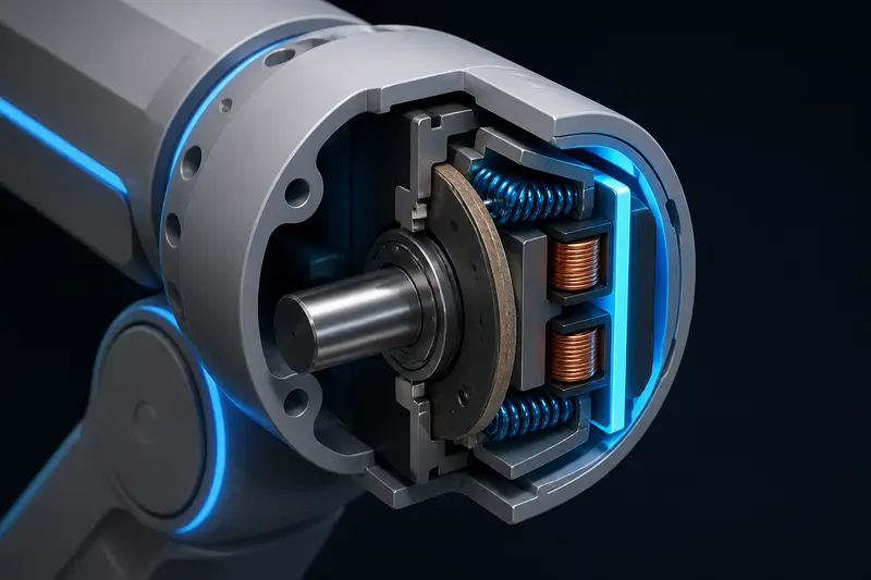
Holding Brake Sizing for a Robot Arm Joint: A Worked Fail-Safe Torque Example
A worked example for sizing a fail-safe holding brake on a robot arm joint: reflecting gravity torque through the gearbox, applying a safety factor, and checking how far the joint drops before the brake engages.
Read more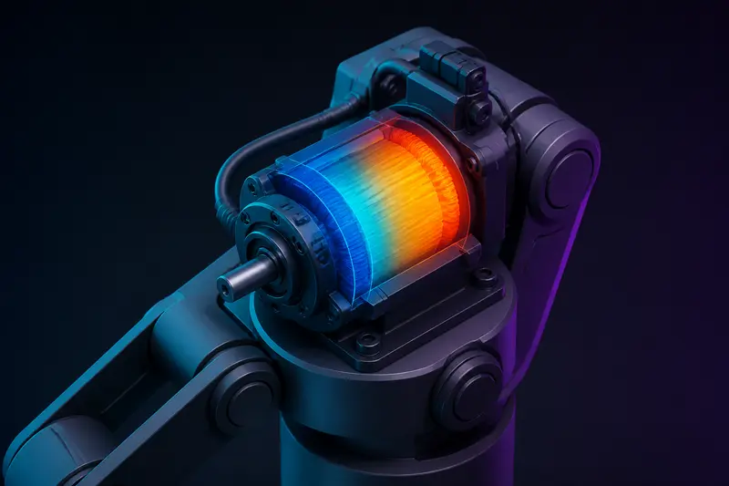
Motor Thermal Duty Cycle Sizing for a Robot Joint: A Worked RMS Current Example
A worked example of motor thermal duty cycle sizing for a robot joint: computing RMS current over a real move-and-hold cycle, comparing it to the continuous rating, and checking the thermal time constant.
Read more
Monte Carlo Localization (Particle Filter) for Mobile Robots: A Worked Numeric Example
A step-by-step Monte Carlo localization example with real numbers: eight particles predicted from odometry, weighted against a landmark-range measurement, and resampled with the low-variance algorithm.
Read more
Cascaded PID Control for Robot Joints: A Worked Bandwidth-Separation Example
Every servo drive nests a current loop inside a velocity loop inside a position loop. A worked example that starts from real motor R, L, J, b numbers and derives the PI gains for all three loops from a chosen bandwidth ratio.
Read more
S-Curve Trajectory for a Robot Joint: A Worked Jerk-Limited Motion Profile
A trapezoidal velocity profile snaps the acceleration on and off, which jolts the joint. Here is how to compute a jerk-limited S-curve trajectory for one joint, with real numbers and the short-move check.
Read more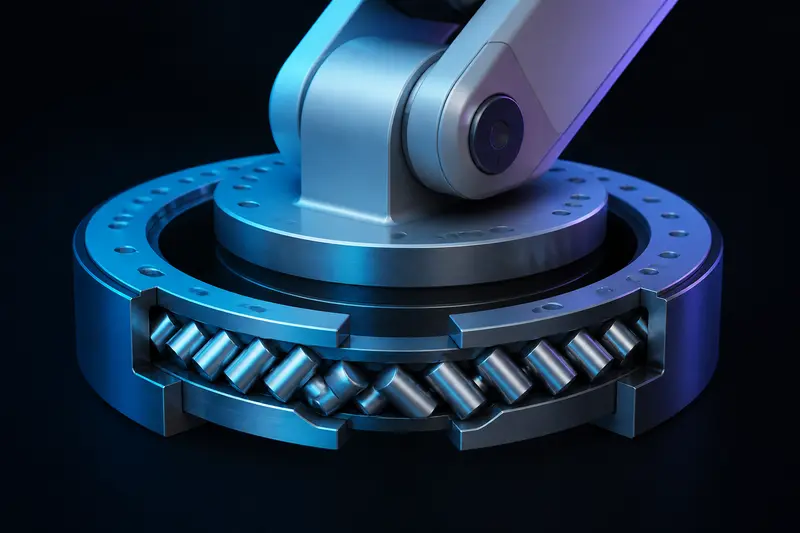
Bearing Selection for Robot Arm Joints: A Worked Moment Load Example
Vendor pages tell you crossed roller bearings handle moment loads. None of them show the arithmetic. Here is the full calculation for a robot arm base joint, including the case for two spaced ball bearings instead.
Read more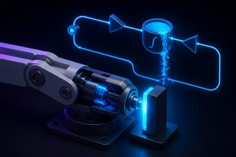
PID Anti-Windup for Robot Joints: A Worked Integrator Windup Example
When a robot joint hits its torque limit, the PID integrator keeps accumulating and the joint overshoots badly. A worked numeric example of integrator windup, then clamping and back-calculation anti-windup with code for a 1 kHz loop.
Read more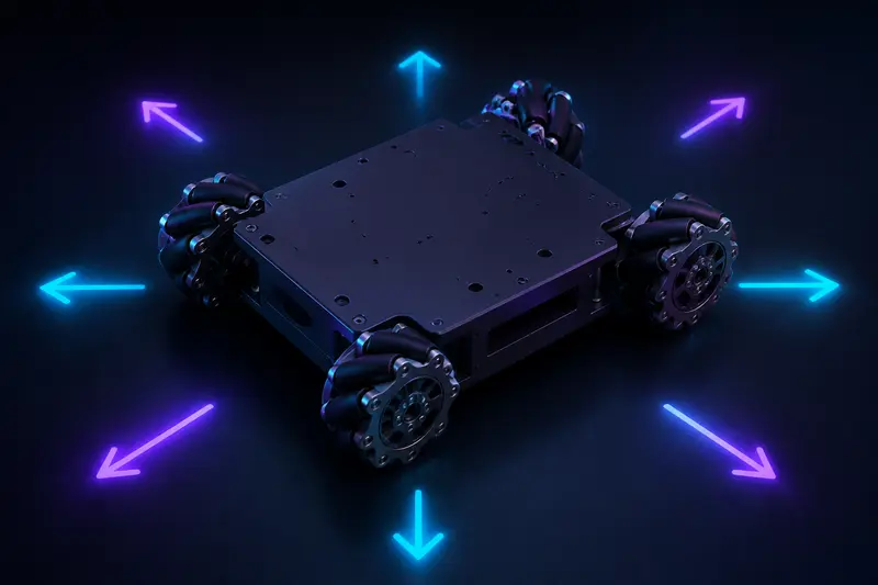
Mecanum Wheel Kinematics: A Worked Example from Velocity Command to Wheel Speeds
Most mecanum kinematics pages stop at the matrix. This one plugs in real geometry numbers, computes wheel speeds in rad/s and RPM for forward, strafe, and combined motion, and shows how to normalize when a motor saturates.
Read more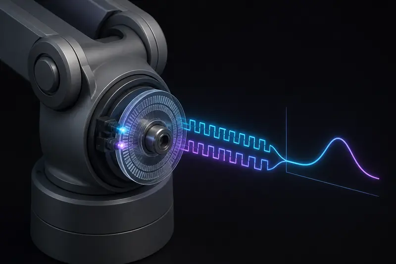
Robot Joint Velocity Estimation from Encoder Counts: Why Finite Differences Get Noisy
Differentiating encoder counts gives you a velocity signal that toggles between zero and full-scale steps. Here is the quantization math that explains why, and four practical estimators with real numbers.
Read more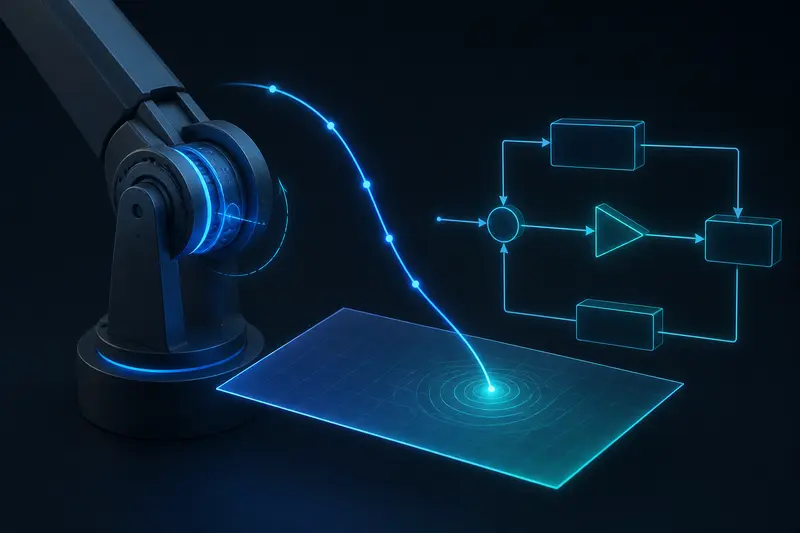
Sliding Mode Control for Robot Arm Joints: A Worked Numeric Example
A worked numeric example of sliding mode control for a single robot arm joint: computing the sliding surface, sizing the switching gain from real inertia and disturbance bounds, and using a boundary layer to remove chattering.
Read more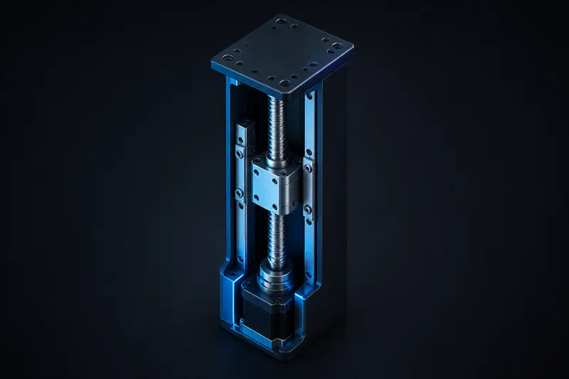
Ball Screw vs Lead Screw for a Robot Linear Actuator: A Worked Torque Sizing Example
A worked sizing example comparing a ball screw and a lead screw for a robot's Z-axis lift actuator: thrust load, drive torque, and the holding-torque tradeoff that decides which one you actually want.
Read more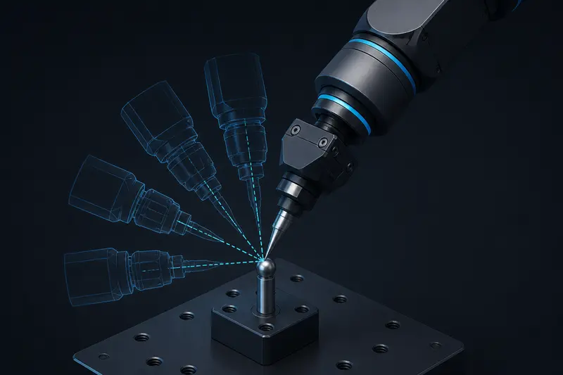
Tool Center Point (TCP) Calibration for Robot Arms: A Worked Pivot Calibration Example
Most robot docs tell you to teach 3-4 poses around a fixed point and let the software calculate the TCP offset. Here is what that calculation actually does, worked through with real numbers.
Read more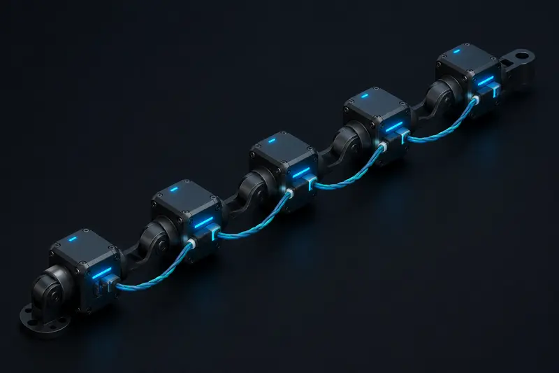
RS-485/Modbus for Robot Joint Networks: Wiring, Addressing, and Polling-Rate Budget
Generic RS-485 wiring guides cover twisted pair and termination resistors, but never show whether a chain of joint drivers can actually keep up with your control loop. Here is the frame-time and polling-budget math.
Read more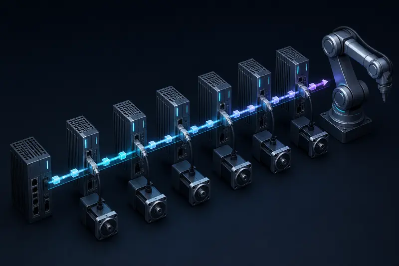
EtherCAT for Robot Joint Networks: How the Cycle-Time Budget Actually Works
A worked cycle-time budget for an EtherCAT robot joint network: frame transmission time, per-slave forwarding delay, and cable propagation combined into a real number, plus what happens when you add one axis too many.
Read more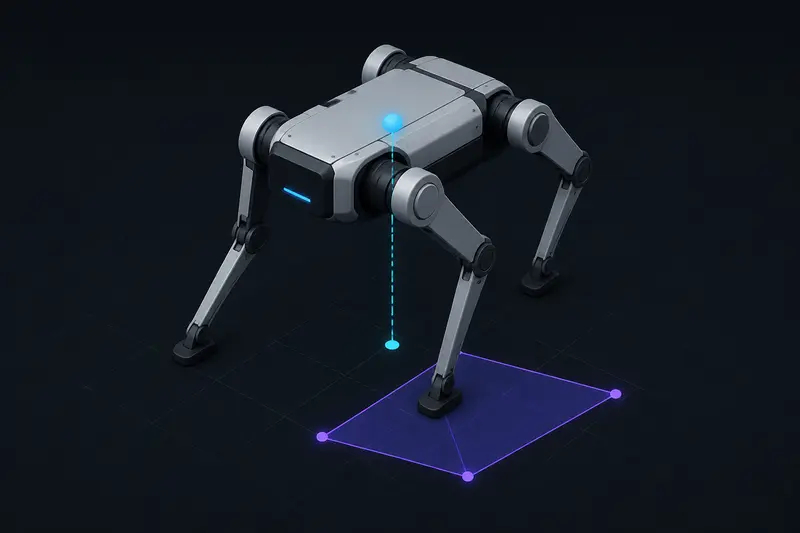
Zero Moment Point for Legged Robot Balance: A Worked Numeric Example
The zero moment point tells you whether a legged robot is about to tip over. Here is the actual formula, a worked numeric example for a quadruped stance, and how to check the result against the support polygon.
Read more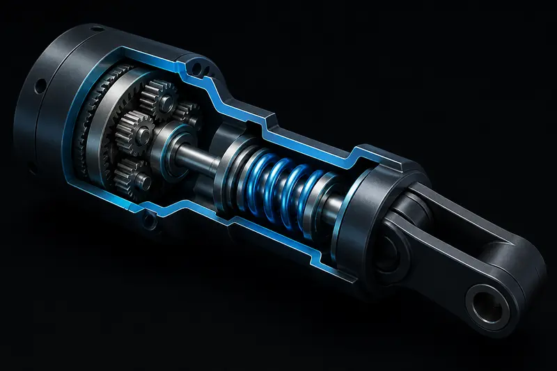
Series Elastic Actuator Design: Sizing the Spring Stiffness for a Robot Joint
Most SEA writeups explain why compliant actuation helps force control but skip the math. Here is a worked example: pick a torsional spring stiffness from your bandwidth and peak torque targets, then calibrate deflection to torque.
Read more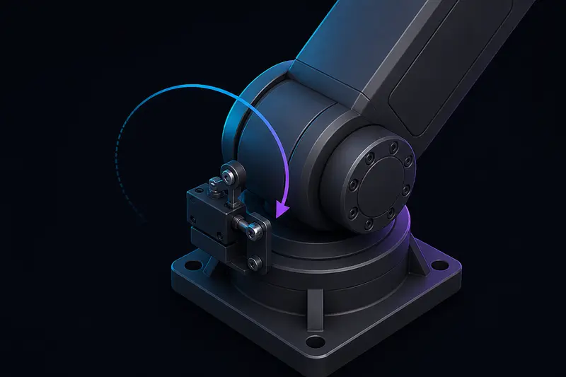
Homing a Robot Arm Joint with a Limit Switch: The Encoder-Offset Math
A limit switch tells a joint it has reached a known point, but a repeatable zero position depends on how you turn that trigger into an encoder offset. Here is the full sequence with real numbers.
Read more
Sensorless BLDC Motor Commutation: A Worked Back-EMF Zero-Crossing Timing Example
Every sensorless BLDC guide says to detect the back-EMF zero crossing and wait 30 electrical degrees. Here is the actual timing math behind that wait, and the blanking-time problem that breaks it at low speed.
Read more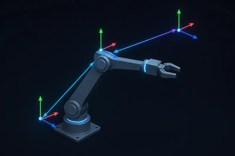
ROS2 tf2 Transforms Explained: A Worked Example (and Why Lookups Fail)
A worked homogeneous-transform example showing exactly how tf2 chains frames, plus the real reasons behind frame-not-found and extrapolation errors.
Read more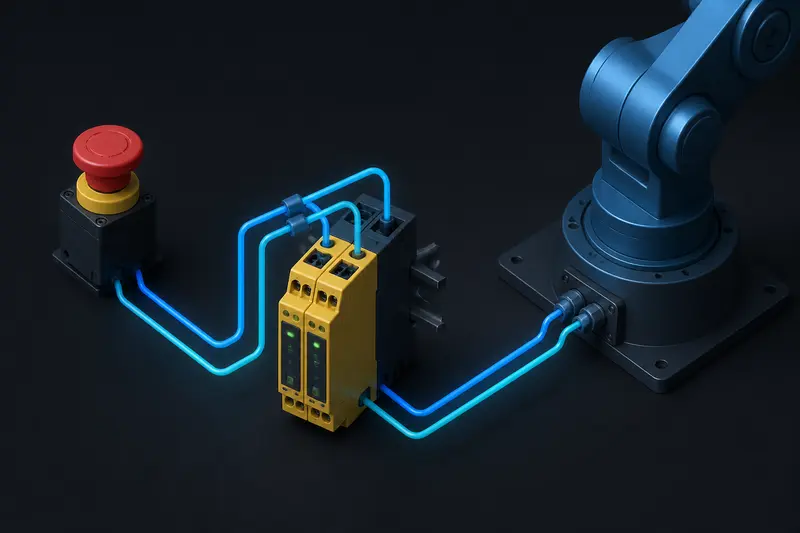
Emergency Stop Circuit Design for a Robot Arm: Category 3 Dual-Channel Wiring Explained
How to wire a Category 3 dual-channel emergency stop into a small robot arm's driver enable line, with a worked stop-response time budget against joint velocity.
Read more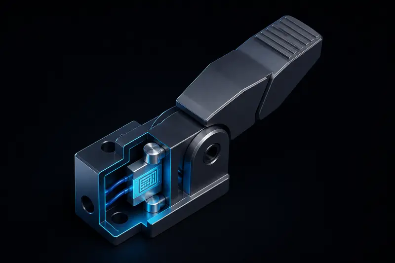
Force Sensing in Robot Grippers: A Worked Load Cell Calibration and PID Force Control Example
How to turn a strain gauge load cell's raw bridge output into a calibrated force reading and close a PID loop on it, with a full worked numeric example.
Read more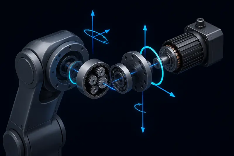
Motor and Gearbox Sizing for a Robot Arm Joint: A Worked Torque Calculation
A worked example of motor and gearbox sizing for a robot arm joint: computing worst-case load torque, applying a safety factor, choosing a gear ratio, and checking the result against a motor's continuous torque rating.
Read more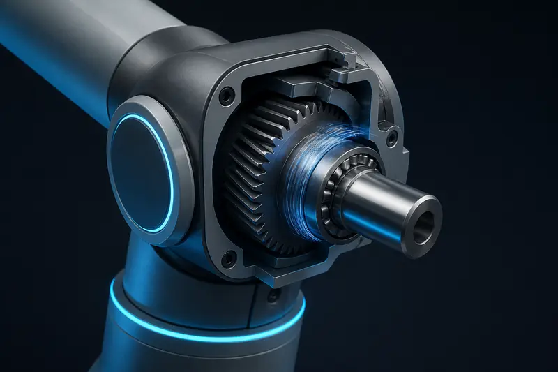
Robot Arm Joint Friction Compensation: A Worked Coulomb and Viscous Example
A worked example showing how to measure Coulomb and viscous friction coefficients on a real robot joint, then add a feedforward compensation term that removes stick-slip jitter near zero velocity.
Read more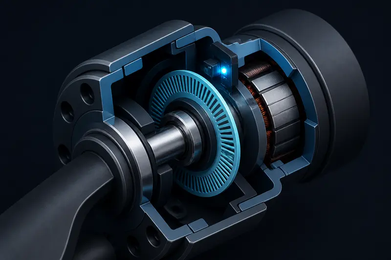
Absolute vs Incremental Encoders for Robot Joints: How to Size the Resolution You Actually Need
A practical guide to choosing between absolute and incremental encoders for robot joints, with a worked example converting a target joint accuracy into encoder bits, PPR, and the effect of gear reduction.
Read more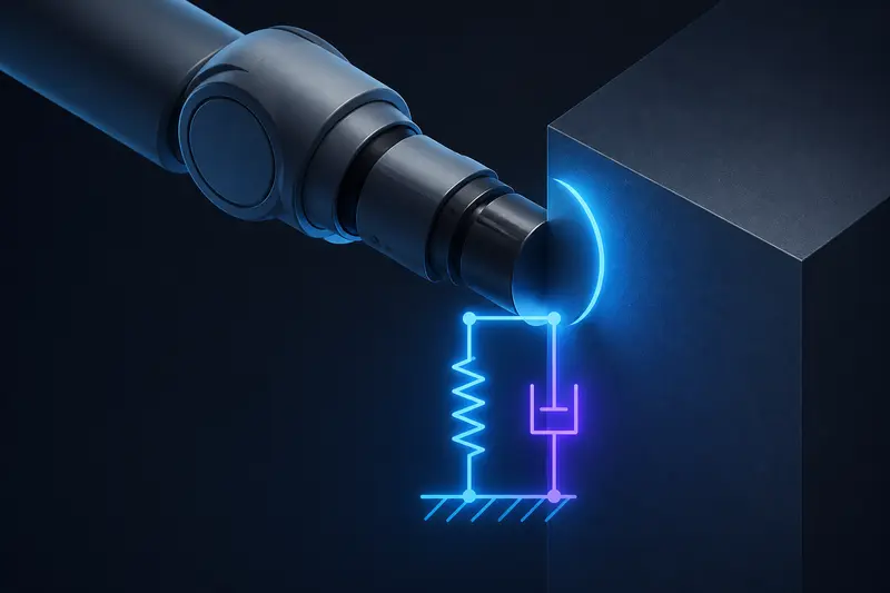
Impedance Control vs Admittance Control for Robot Arms: A Worked Numeric Example
Impedance control and admittance control both make a robot arm compliant, but they compute opposite things. A worked numeric example with real K, D, and M values shows exactly what each one commands.
Read more
CAN Bus for Robot Joint Networks: Wiring, Bit Timing, and Bus Load Explained
Most CAN bus writeups explain the protocol in general terms. Here we work through the actual bit-timing and bus-load numbers for a 6-joint robot arm, and show what happens when you get termination or message rate wrong.
Read more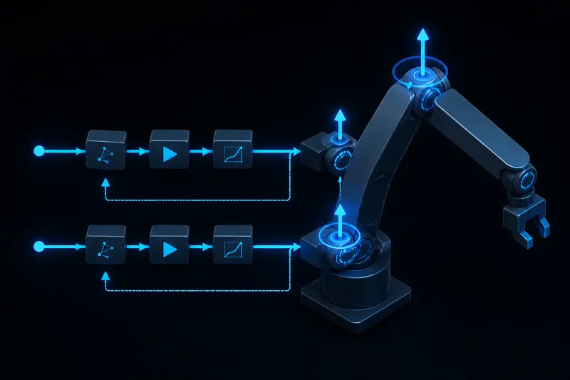
Computed Torque Control for Robot Arms: A Worked Numeric Example
A worked numeric example of computed torque control for a two-link robot arm: building the M(q), C(q,qdot), G(q) terms, canceling them with an inverse dynamics model, and reducing tracking error to a simple double integrator.
Read more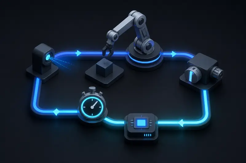
Real-Time Considerations in Robot Control Loops: Budgeting Jitter and Choosing Your Loop Rate
A concrete look at real-time considerations in robot control loops: what jitter actually is, how to measure it with real timer code, and how to compute the jitter budget your gains can survive before a joint starts to oscillate.
Read more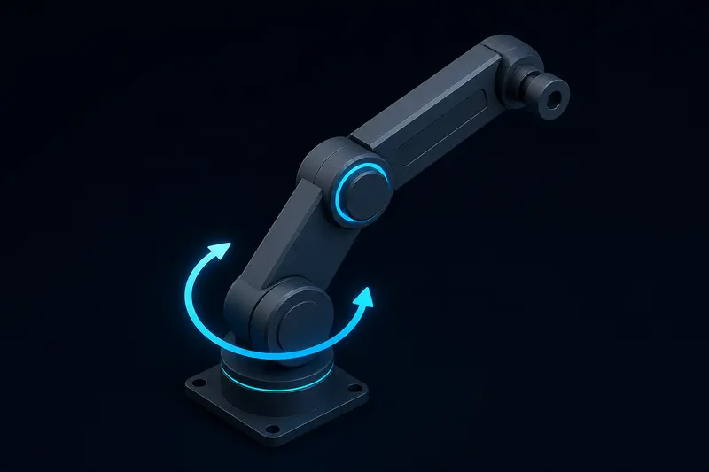
Robot Arm Gravity Compensation: A Worked Torque Calculation Example
A worked numeric example of robot arm gravity compensation: deriving the torque formula for a one-link and a two-link arm, then adding it as a feedforward term next to a PD position loop.
Read more
Extended Kalman Filter SLAM (EKF-SLAM) Explained: A Worked Numeric Example
A step-by-step EKF-SLAM example with real numbers: the joint state vector, covariance matrix, measurement Jacobian, and Kalman gain for a differential-drive robot mapping two landmarks.
Read more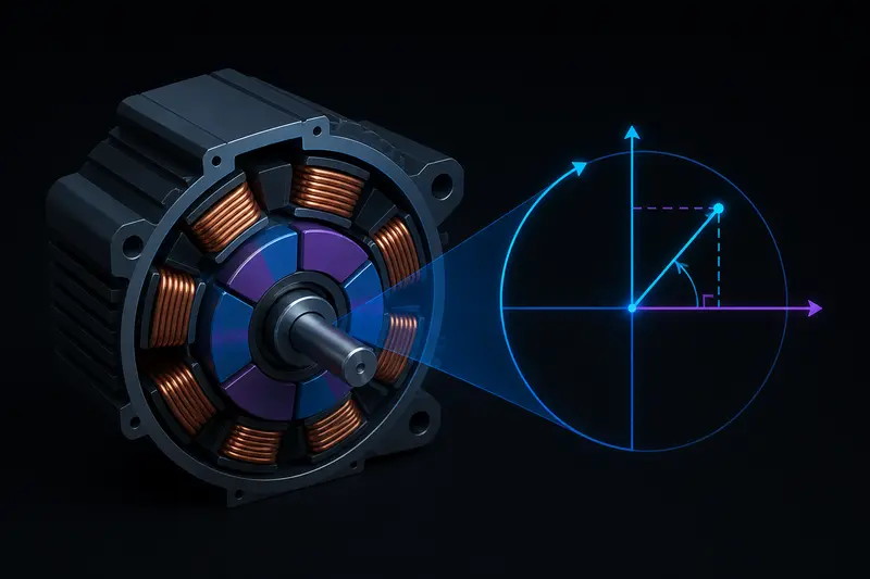
Field-Oriented Control (FOC) for BLDC Motors Explained: A Worked Clarke/Park Example
Field-oriented control turns three noisy phase currents into two clean numbers, Id and Iq, that you can control independently. Walk through the Clarke and Park transforms with an actual worked example.
Read more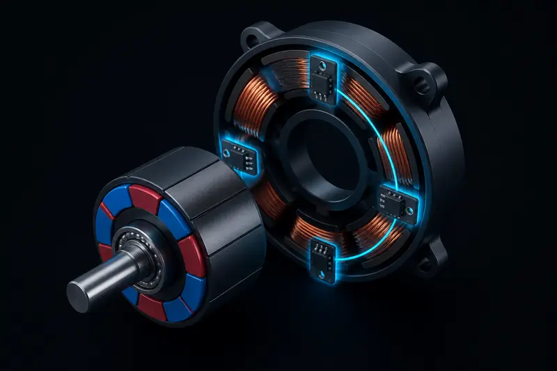
BLDC Hall Sensor Commutation Explained: Building the Six-Step Table from Scratch
How three hall sensors and a six-state lookup table turn a brushless DC motor into something you can commutate with simple digital logic, plus the classic wrong-direction failure and how to fix it.
Read more
ROS2 QoS Settings Explained: Why Your Subscriber Gets Zero Messages
ROS2 QoS settings explained through the classic mismatch bug: a subscriber that compiles, connects, and receives nothing, with the diagnostic commands and fix.
Read more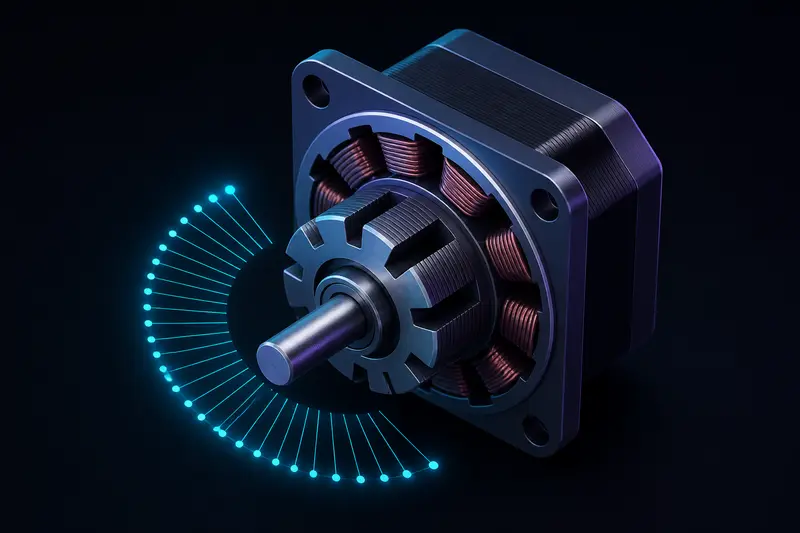
Stepper Motor Microstepping Explained: Torque, Resolution, and Missed Steps
A practical look at stepper motor microstepping: the holding-torque-per-microstep formula, real driver chip tradeoffs, and how missed steps actually happen under load.
Read more
Differential Drive Robot Kinematics and Wheel Odometry: A Worked Example
A practical walkthrough of differential drive robot kinematics: the forward kinematics equations, the discrete odometry update used in real firmware, and a worked numeric example showing how encoder noise and wheel slip turn into real position error.
Read more
ROS2 Executors and Callback Groups Explained: Why One Slow Callback Can Stall Your Robot
A worked example of how ROS2 executors and callback groups schedule work, including the classic bug where one slow sensor callback silently stalls a robot's control loop.
Read more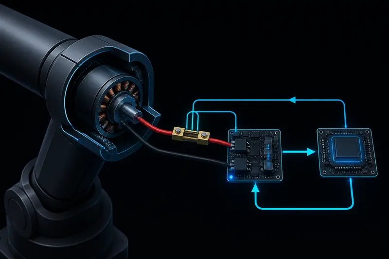
Torque Control for Robot Arm Joints: From Motor Current to Commanded Torque
How to go from a raw current sensor reading to a controlled joint torque: the Kt constant, a cascaded current/velocity/position control structure, and a worked PI current-loop tuning example.
Read more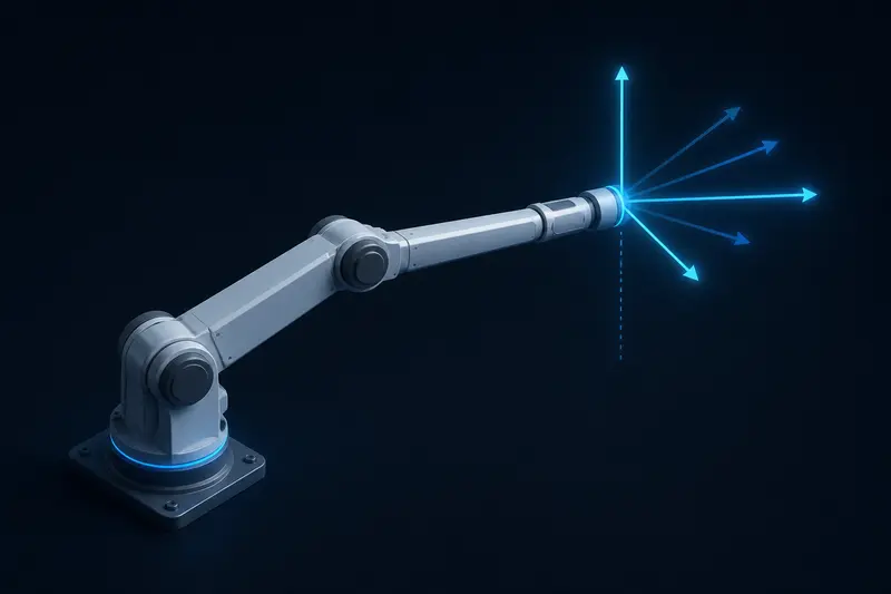
Robot Arm Singularity Avoidance with the Jacobian: A Worked Example
A worked numeric example of robot arm singularity avoidance: computing the Jacobian determinant for a planar arm, watching it collapse near full extension, and comparing plain pseudo-inverse against damped least squares.
Read more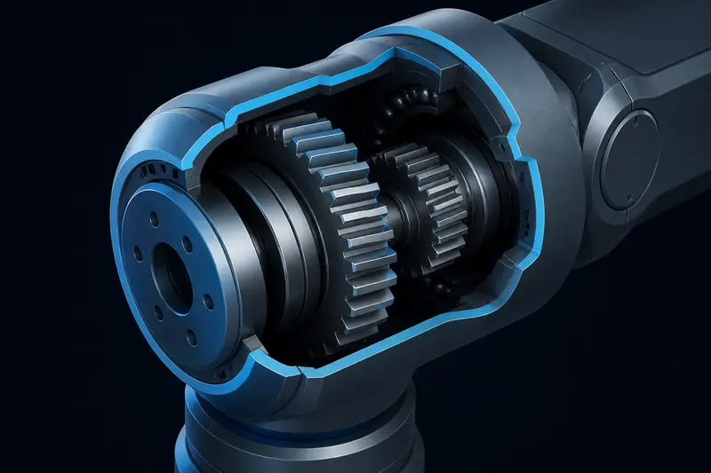
Gearbox Backlash Compensation for Robot Arm Joints: Measuring and Correcting Mechanical Play
How to measure gearbox backlash from encoder position error at direction reversals, and how to compensate for it in software with dead-band inversion and lookup tables.
Read more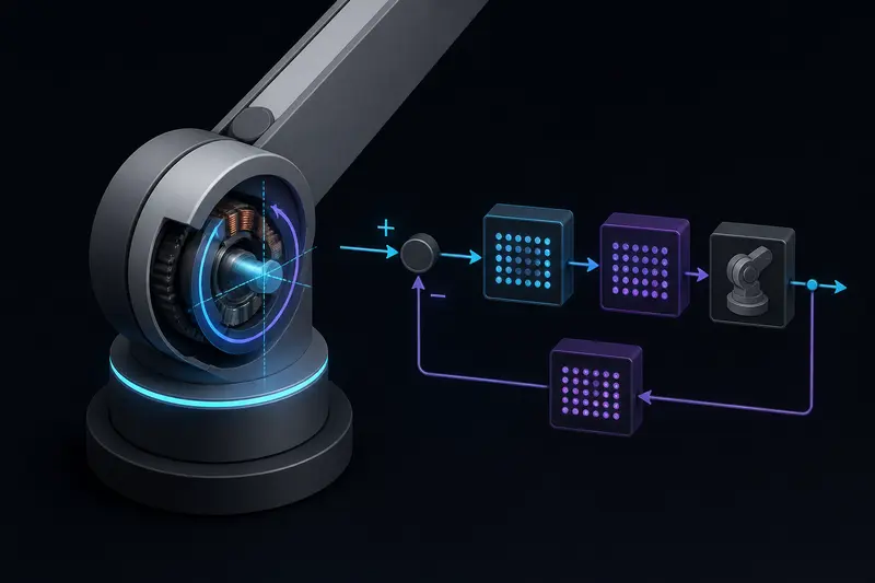
LQR Control for Robot Arms: A Practical Introduction
PID tuning gets you far on a single robot joint, but it runs out of headroom once coupling and disturbances matter. Here is how LQR control for robot arms works, with the state-space model and Q/R tuning spelled out.
Read more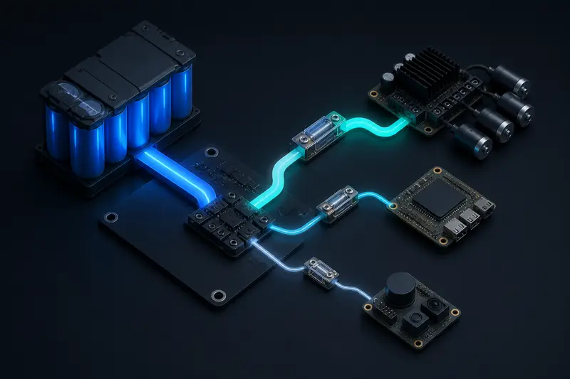
Power Budgeting for Mobile Robots: From Component List to Wire Gauge
A practical guide to power budgeting for mobile robots: separating peak from average current, sizing battery capacity, and translating the resulting numbers into wire gauge and fuse choices.
Read more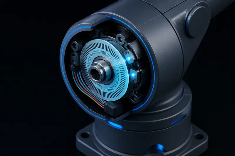
Quadrature Encoder Wiring for a 6-DOF Robot Arm: A Practical Guide
A practical walkthrough of wiring quadrature encoders on a 6-DOF robot arm: channel A/B connections, counts-per-revolution to joint-angle math after a gear reduction, debouncing, and index-pulse homing.
Read more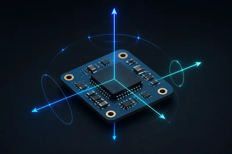
IMU Sensor Fusion Basics: Combining Accelerometer and Gyroscope Data
A practical introduction to IMU sensor fusion basics: why accelerometers and gyroscopes fail on their own, and how complementary and Kalman filters combine them into a stable orientation estimate.
Read more
Choosing a Battery for a Quadruped Robot: A Practical Sizing Guide
A practical guide to sizing a quadruped robot's battery: matching voltage to your motor drivers, capacity to your runtime target, and discharge rate to peak leg torque demands.
Read more
Trajectory Planning for Robotic Arms: From Waypoints to Smooth Motion
A practical guide to trajectory planning for robotic arms: joint-space vs Cartesian planning, trapezoidal and S-curve velocity profiles, and common pitfalls that cause jerky or unsafe motion.
Read more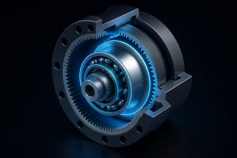
Harmonic Drive vs Planetary Gearbox: Choosing the Right Reduction for a Robot Joint
A practical comparison of harmonic drives and planetary gearboxes for robot joints, covering backlash, stiffness, torque density, efficiency and cost so you can pick the right one.
Read more
SLAM Basics for Mobile Robots: How Robots Map and Localize at the Same Time
A practical introduction to SLAM basics for mobile robots: the chicken-and-egg problem, the main algorithm families (EKF-SLAM, particle filters, graph-based SLAM), and why loop closure matters.
Read more
ROS2 Nodes and Topics Explained: How Robot Software Talks to Itself
A practical walkthrough of ROS2 nodes, topics, publishers, and subscribers, with working Python examples and the DDS concepts that make it all work.
Read more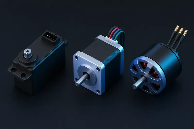
Servo vs Stepper vs BLDC Motor for Robotics: Choosing the Right Actuator
A practical comparison of servo, stepper, and BLDC motors for robotics, covering torque density, positional accuracy, cost, and how much control complexity each option demands.
Read more
Kalman Filter for Robot State Estimation: A Practical Introduction
A practical walkthrough of the Kalman filter for robot state estimation: the predict-update cycle, the core equations, and a worked 1D example you can extend to a real robot.
Read more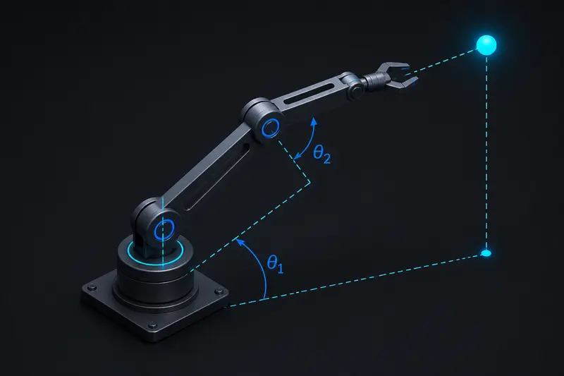
Inverse Kinematics Explained: How Robotic Arms Solve for Joint Angles
A practical walkthrough of inverse kinematics: what it solves, why it's harder than forward kinematics, and how analytical, Jacobian, and CCD methods work in practice.
Read more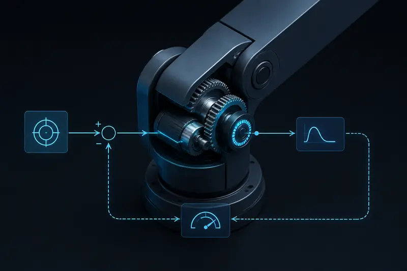
PID Controller Tuning for Robotic Arms: A Practical Guide
A hands-on walkthrough of PID controller tuning for robotic arms: what each term does, how to tune by hand or with Ziegler-Nichols, and how to fix common failure modes.
Read moreNo articles match your search.