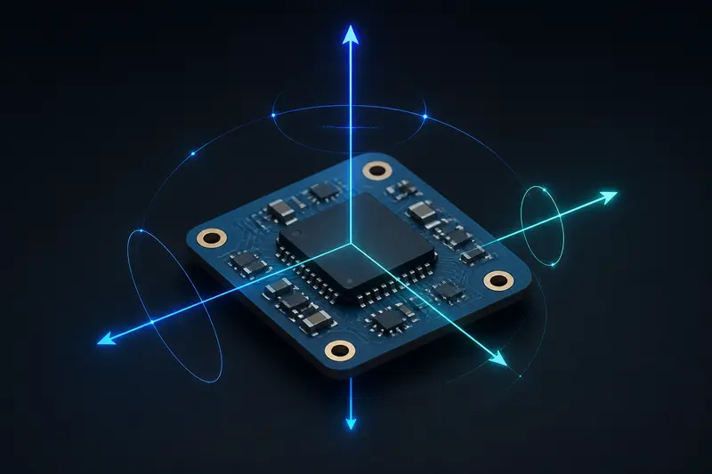
An inertial measurement unit (IMU) is the sensor most mobile robots, drones, and balancing robots rely on to know which way is up. But a raw IMU reading is not usable on its own. Understanding IMU sensor fusion basics means understanding why each individual sensor inside the IMU fails in a different way, and how combining them cancels out those failures.
What an IMU Actually Measures
A typical IMU used in robotics bundles two or three sensors:
- Accelerometer - measures linear acceleration along X, Y, Z, including gravity.
- Gyroscope - measures angular velocity (rate of rotation) around each axis.
- Magnetometer (optional) - measures the local magnetic field vector, used as a heading reference.
Neither the accelerometer nor the gyroscope directly measures orientation (roll, pitch, yaw). Orientation has to be derived, and each sensor derives it with a different flaw.
The Accelerometer's Problem: Noise and Motion
At rest, an accelerometer reads gravity, so you can compute roll and pitch from the gravity vector using basic trigonometry:
roll  = atan2(accel_y, accel_z)
pitch = atan2(-accel_x, sqrt(accel_y^2 + accel_z^2))
This works well when the sensor is stationary. The problem is that the accelerometer measures total specific force, not gravity alone. The moment the robot accelerates, brakes, or vibrates, that motion adds directly into the reading and corrupts the tilt estimate. A robot braking hard will briefly appear to be pitching forward even if it is perfectly level. Accelerometer-only tilt estimates are also noisy on a sample-by-sample basis, especially near motors and gearboxes.
The Gyroscope's Problem: Drift
A gyroscope measures angular velocity, so you can integrate it over time to get orientation:
angle(t) = angle(t-1) + gyro_rate * dt
This is smooth and immune to linear acceleration or vibration, which makes it excellent for short-term, high-frequency motion. The catch is integration. Every gyroscope has a small constant bias error, often a fraction of a degree per second, and integrating that bias over time causes the estimated angle to drift steadily away from the true value. A cheap MEMS gyro left to integrate alone can drift tens of degrees within a minute of operation.
IMU Sensor Fusion Basics: Combining the Two
The core idea behind IMU sensor fusion is simple: use the gyroscope for what it is good at (fast, smooth, short-term changes) and the accelerometer for what it is good at (long-term, drift-free reference), then blend the two so each one corrects the other's weakness.
The Complementary Filter
The complementary filter is the simplest and most widely used fusion technique for embedded robotics, because it requires no matrix math and runs comfortably on a microcontroller. For a single axis:
angle = alpha * (angle + gyro_rate * dt) + (1 - alpha) * accel_angle
Here alpha is typically close to 0.98. The gyro-integrated angle dominates on a sample-to-sample basis (preserving responsiveness), while a small correction toward the accelerometer's angle is applied every cycle (preventing long-term drift). The two error sources are, in effect, complementary: the gyro is accurate short-term and wrong long-term, the accelerometer is the opposite, so a weighted blend suppresses both.
Tuning alpha is a tradeoff. Push it toward 1.0 and the filter trusts the gyro more, giving a smoother but slower-to-correct estimate. Push it lower and the filter reacts faster to accelerometer corrections but becomes more sensitive to vibration and transient accelerations.
The Kalman Filter Approach
A Kalman filter formalizes the same idea with an explicit statistical model. Instead of a fixed blending constant, it maintains an estimate of orientation plus its uncertainty (covariance), predicts forward using the gyroscope, and updates that prediction using the accelerometer measurement weighted by how much each sensor is currently trusted. When the robot is accelerating hard, the filter can be told to reduce its confidence in the accelerometer step, so a good Kalman or extended Kalman filter (EKF) implementation, or the closely related Madgwick and Mahony filters common in flight controllers, adapts its trust in the accelerometer based on how much linear acceleration is currently present. This adaptive weighting is the main practical advantage over a fixed-alpha complementary filter, at the cost of more computation and more parameters to tune. Readers looking for the general estimation framework behind this should see our article on Kalman filter state estimation, since orientation fusion is really a special case of the same predict-update cycle used for position and velocity estimation.
Adding a Magnetometer for Heading
Both the complementary filter and a basic 6-axis Kalman filter can correct roll and pitch using gravity, but neither can correct yaw (heading), because gravity gives no information about rotation around the vertical axis. A magnetometer measures the ambient magnetic field vector and provides that missing heading reference, at the cost of being sensitive to nearby ferrous metal and motor currents, which is why magnetometer calibration and placement matters more than either accelerometer or gyroscope calibration.
Practical Considerations
- Sample rate matters. Gyroscope integration error grows with a larger
dt, so run the fusion loop as fast as your microcontroller and IMU output data rate reasonably allow, typically 100 Hz to 1 kHz for a balancing robot or drone. - Calibrate the gyroscope bias at startup. Average several hundred samples while the robot is stationary and subtract that offset before integrating.
- Watch for gimbal lock if using Euler angles. Many production fusion filters represent orientation as a quaternion internally and only convert to roll/pitch/yaw for human-readable output, because quaternions avoid the singularity that occurs when pitch approaches 90 degrees.
- Vibration isolation helps more than filtering. No fusion algorithm fully compensates for an accelerometer that is mechanically shaking against a chassis; physically damping the IMU mount reduces noise before it ever reaches the filter.
Choosing an Approach
For a self-balancing robot, a simple drone, or a hobbyist project, a complementary filter is usually enough and is far easier to debug. For applications where GPS or other position sensors also need to be fused, or where accuracy under aggressive motion matters, an extended Kalman filter or a Madgwick filter is worth the added complexity. Either way, the underlying principle of IMU sensor fusion basics stays the same: no single inertial sensor gives you a trustworthy orientation on its own, but a gyroscope and an accelerometer blended together compensate for each other's weaknesses well enough to run real-time robot control loops.
Building or studying robotics?
Arcbotix publishes practical guides on robotics engineering, control systems and real-world builds. Explore more articles on the blog.