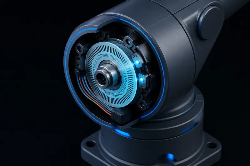
Quadrature Encoder Wiring for a 6-DOF Robot Arm
Most 6-DOF robot arm tutorials online stop at hobby servos: a potentiometer buried inside a sealed case, no real feedback you can read, and no way to close a tight position or velocity loop. Once you move to DC gearmotors or BLDC joints driven by a real controller, you need actual encoder feedback, and that means wiring and decoding a quadrature encoder correctly on every joint. This guide covers the wiring, the counts-per-revolution math after your gear reduction, debouncing, and index-pulse homing needed to get six joints reporting trustworthy angles.
How a Quadrature Encoder Actually Works
A quadrature encoder outputs two square-wave signals, channel A and channel B, offset by 90 electrical degrees. As the shaft rotates, a decoder watches the order in which A and B transition high and low. If A leads B, the shaft is turning one direction; if B leads A, it is turning the other. This is what makes quadrature decoding direction-aware, unlike a single-channel pulse counter that only tells you speed.
Each full encoder cycle (one rise and fall of both A and B) is called one count, but most decoding schemes read all four edges per cycle, giving 4x the encoder's native pulses-per-revolution (PPR) rating. A 500 PPR encoder therefore yields 2000 counts per revolution (CPR) when decoded on all four edges. This 4x multiplication is the single most common source of confusion when people calculate joint resolution incorrectly.
Wiring: What's on the Connector
Most incremental encoders used on small robot arm joints (magnetic or optical) expose five wires:
- VCC - typically 5V, sometimes 3.3V. Check the datasheet; feeding 5V into a 3.3V-only encoder will damage it.
- GND - common ground, shared with your microcontroller.
- Channel A - first quadrature signal.
- Channel B - second quadrature signal, 90 degrees out of phase with A.
- Index (Z) - one pulse per full revolution, used for homing (not present on every encoder model).
Wiring practice that actually matters on a 6-joint arm, where cable runs are long and share space with motor power:
- Route encoder signal wires away from motor phase wires or PWM lines. Running them in the same bundle couples switching noise directly into your edge counts, causing phantom counts under load.
- Use twisted pairs for A and B where cable runs exceed roughly 30cm, and keep a solid ground return alongside them.
- If a joint is far from the controller board (common for wrist and end-effector joints on a 6-DOF arm), add a line receiver or a simple RC low-pass filter (around 1nF to 4.7nF with a few hundred ohms) on each channel to strip high-frequency noise before it reaches your microcontroller's input pin.
- Add a 100nF decoupling capacitor across VCC and GND right at the encoder connector to suppress supply noise.
Reading the Signal: Interrupts vs Hardware Timers
There are two practical ways to decode quadrature on a microcontroller-driven joint:
1. Interrupt-Based Software Decoding
Attach interrupts to both channel A and channel B pins, and on every edge, read both pin states and update a count based on the transition table. A minimal decode table looks like this in C:
volatile long count = 0;
int8_t lookup[16] = {0,-1,1,0,1,0,0,-1,-1,0,0,1,0,1,-1,0};
volatile uint8_t prevState = 0;

void encoderISR() {
  uint8_t state = (digitalRead(PIN_A) << 1) | digitalRead(PIN_B);
  uint8_t index = (prevState << 2) | state;
  count += lookup[index];
  prevState = state;
}
This works fine for one or two joints on a fast microcontroller, but six joints each generating interrupts on every edge (up to thousands of interrupts per second at speed) will start eating into your control loop's timing budget, an issue that compounds the concerns covered in PID controller tuning for robotic arms: a control loop with encoder interrupts firing unpredictably at high joint speed gets exactly the kind of timing jitter that erodes tuning margins.
2. Hardware Quadrature Decoders
For a 6-joint arm, dedicated hardware decoding is the more reliable path. Options include:
- Microcontrollers with built-in quadrature encoder peripherals (many STM32 and some ESP32 timer channels support this directly in hardware, decoding all edges without CPU interrupts).
- Standalone quadrature counter ICs, such as the LS7366R, which connects over SPI and offloads all edge counting to dedicated hardware, letting you poll six of them on a shared bus without burning interrupt cycles.
Hardware decoding is worth the extra part cost once you are past a two or three joint prototype, because it removes encoder counting entirely from your real-time budget.
From Counts to Joint Angle
The math that converts raw encoder counts into a usable joint angle has three steps, and skipping the gear ratio step is the most common mistake in DIY arm builds:
- Counts per motor revolution: PPR x 4 (from quadrature decoding) = CPR.
- Counts per output-shaft revolution: CPR x gear ratio. A 500 PPR encoder on the motor shaft behind a 100:1 gearbox gives 500 x 4 x 100 = 200,000 counts per output revolution.
- Counts to degrees: joint_angle_degrees = (raw_count / counts_per_output_rev) x 360.
For the 100:1 example above, each count corresponds to 360 / 200,000 = 0.0018 degrees, well within useful resolution for most arm joints. If your encoder sits on the output shaft instead of the motor shaft (less common, but true for some direct-drive or harmonic-drive designs discussed in harmonic drive vs planetary gearbox setups), skip the gear ratio multiplication entirely, since the encoder is already reading the true joint angle.
Index Pulse Homing
Incremental encoders report relative position only. On power-up, every joint's count register starts at zero regardless of the arm's actual pose, so you need a homing routine before trusting any angle reading. The index (Z) channel, when present, pulses once per revolution and gives you a repeatable zero reference:
- Slowly rotate the joint toward a mechanical limit switch or hard stop at low speed.
- Once triggered, reverse slightly off the limit, then rotate slowly until the index pulse fires.
- Zero the count register at that exact index pulse. This is your repeatable home position for that joint.
- Store the offset between this electrical zero and the joint's physical zero (usually defined by your kinematic model) so forward and inverse kinematics calculations start from a consistent reference.
Without an index channel, you must home purely against a limit switch or hard stop each time, which is less repeatable since switch actuation point varies slightly with approach speed and mechanical wear. For any joint feeding into inverse kinematics calculations, index-based homing is worth the extra encoder cost, since IK error compounds when your joint zero reference drifts between power cycles.
Common Wiring Mistakes on Multi-Joint Arms
- Shared ground loops: if each joint's encoder ground returns through a long, thin wire shared with motor return current, voltage drop across that wire shows up as noise on the encoder signal. Use a dedicated, low-impedance ground path for encoder returns.
- Miscounting resolution: forgetting the 4x quadrature multiplier or the gear ratio leads to a joint that appears to move 100 times more or less than commanded.
- Ignoring encoder voltage rating: mixing 3.3V logic encoders with 5V pull-ups without level shifting risks damaging the encoder's output driver over time.
- No noise filtering on long cable runs: wrist and gripper joints on a 6-DOF arm often have the longest cable runs back to the controller, and are the joints most likely to show phantom counts under motor load if left unfiltered.
Conclusion
Wiring quadrature encoders correctly on a 6-DOF arm comes down to three things: keep encoder signal wiring physically and electrically separated from motor power, do the CPR-and-gear-ratio math correctly so raw counts translate into real degrees, and give every joint a repeatable homing reference before trusting its reported angle. Get these right per joint, and the encoder feedback becomes a solid foundation for whatever position or velocity control loop runs on top of it.
Building or studying robotics?
Arcbotix publishes practical guides on robotics engineering, control systems and real-world builds. Explore more articles on the blog.