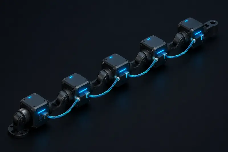
RS-485/Modbus shows up constantly in robot joint networks because the drivers are cheap, the wiring is a two-wire twisted pair, and most stepper and servo driver boards already speak Modbus RTU out of the box. Most wiring guides stop at cable specs and termination resistors. What they skip is the question that actually determines whether the protocol works for your robot: given N joint drivers on one bus at a given baud rate, what polling rate can you actually sustain, and does it meet your control loop's update rate?
RS-485/Modbus wiring for a robot joint network
RS-485 is a differential two-wire bus: A (non-inverting) and B (inverting), plus a common ground reference. Every joint driver's A terminal connects to every other joint driver's A terminal, and likewise for B, forming a single linear daisy chain, not a star. A star topology causes reflections at the branch points and will corrupt frames intermittently, which is a common source of "it works until I add the fourth joint" bugs.
- Cable: shielded twisted pair, 22-24 AWG, characteristic impedance close to 120 ohms (e.g. Belden 9841 or equivalent).
- Termination: a 120-ohm resistor across A/B at each physical end of the chain only, never at intermediate nodes.
- Ground: a common reference wire between all nodes, plus shield grounded at one end only to avoid ground loops.
- Bias resistors: pull-up on A and pull-down on B (typically 560 ohm to 1 k ohm) at one node keep the bus in a known idle state when no driver is transmitting, preventing false frame detection.
- Device limit: standard RS-485 transceivers support 32 unit loads on one segment. Many modern transceivers are quarter or eighth unit load, which lets you exceed 32 physical devices on the same bus, but check the transceiver datasheet before assuming this.
Every joint driver gets a unique Modbus slave address (1-247), typically set with onboard DIP switches or a one-time serial command at commissioning. Address 0 is reserved for broadcast messages that all slaves accept without replying.
Modbus RTU frame time: the number that actually matters
Modbus RTU is a master-polls-slave protocol: the controller (master) sends a request frame, the addressed joint driver replies, and only then can the master poll the next joint. There is no multi-master arbitration and no broadcast telemetry like CAN's message-based model, so your achievable update rate is set entirely by how long each request/response pair takes.
A Modbus RTU frame is built from 11-bit character frames (1 start bit, 8 data bits, 1 parity or extra stop bit, 1 stop bit) at your chosen baud rate. Frame transmission time in milliseconds:
t_frame (ms) = (bytes_in_frame * 11 bits) / baud_rate * 1000
A typical "read joint position and current" request is 8 bytes (address, function code, register address, register count, 2-byte CRC), and the response carrying two 16-bit registers is 9 bytes. At 115200 baud:
t_request = (8 * 11) / 115200 * 1000 = 0.76 ms
t_response = (9 * 11) / 115200 * 1000 = 0.86 ms
To that you must add the turnaround delay: the time the slave's microcontroller takes to decode the request, read its sensors, and start transmitting the reply. This is driver-specific but commonly 1-3 ms for a joint driver running its own current-loop firmware. Modbus RTU also defines a mandatory inter-frame silence of 3.5 character times to mark frame boundaries, which at 115200 baud is about 0.33 ms and is small enough to fold into your turnaround margin.
t_cycle_per_joint = t_request + t_turnaround + t_response
Using a 2 ms turnaround: t_cycle_per_joint = 0.76 + 2.0 + 0.86 = 3.62 ms.
Worked example: 6-joint arm on a shared bus
For a 6-DOF arm polling every joint once per control cycle:
t_total = 6 * 3.62 ms = 21.7 ms
That caps your update rate at roughly 1 / 0.0217 s = 46 Hz. If your position control loop needs 100 Hz (10 ms per cycle), this bus configuration cannot keep up, no matter how well it is wired. You have three practical levers:
- Raise the baud rate. Modbus RTU over RS-485 commonly runs to 921600 baud on short, well-terminated runs. Going from 115200 to 460800 baud cuts frame time roughly 4x, moving t_cycle_per_joint from 3.62 ms toward 2.4 ms (turnaround now dominates, not the wire time), for a 6-joint total near 14.6 ms and about 68 Hz.
- Reduce turnaround. If the joint driver firmware can reply immediately from a pre-computed register instead of blocking on a fresh ADC read, turnaround can often drop under 1 ms, which matters more once baud rate is already high.
- Split the bus. Put 3 joints on one RS-485 segment and 3 on a second, each with its own UART on the controller, and poll both segments in parallel. This roughly halves the effective chain length for the same per-joint frame time.
This is the same kind of budget arithmetic covered for CAN bus timing in CAN Bus for Robot Joint Networks and for EtherCAT in EtherCAT for Robot Joint Networks, and the comparison is worth being explicit about: CAN broadcasts short frames with hardware arbitration and no per-node turnaround wait, so it scales to more nodes at a given update rate; EtherCAT processes frames on the fly through every slave in one pass, which is why it can hit kHz-class cycle times on many axes. Modbus RTU's strict poll-and-wait model is the simplest to wire and debug, but it does not scale past a handful of joints once you need triple-digit control rates.
When RS-485/Modbus is the right choice
Modbus RTU remains a solid pick when the update rate requirement is modest: a gripper, a slow-moving gantry axis, or a joint whose position loop runs locally on the driver and only needs a setpoint update at 20-50 Hz from the host. It is also the easiest protocol to bring up with a bench multimeter and a USB-RS485 adapter, since most Modbus master libraries (pymodbus, libmodbus) will talk to a driver in a few lines of code. For a fast multi-joint arm running a tight position or torque loop above roughly 100 Hz across all joints, budget the frame-time arithmetic above before committing to the bus, or plan to move to CAN or EtherCAT instead.
A quick sanity check before wiring anything: multiply your target control rate's period (ms) by the number of joints, and see how much time per joint that leaves. If it is less than roughly 2-3 ms per joint, RS-485/Modbus RTU is the wrong bus for that update rate, regardless of how carefully you terminate the cable.
Building or studying robotics?
Arcbotix publishes practical guides on robotics engineering, control systems and real-world builds. Explore more articles on the blog.