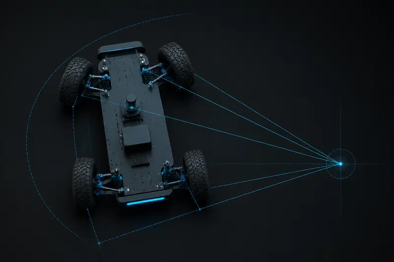
Any robot that steers with two front wheels on a common axle, like an RC car chassis, a warehouse tugger, or an outdoor rover with a car-like drivetrain, runs into the same problem the moment you turn: the inner and outer front wheels do not travel on circles of the same radius. If you steer both wheels to the same angle, at least one of them scrubs sideways against the ground every time you turn. Ackermann steering kinematics is the geometry that fixes this by giving each front wheel a slightly different angle. This article works through the actual numbers for a real chassis.
The Ackermann steering geometry
A car-like robot has a fixed wheelbase L (distance from front axle to rear axle) and a fixed track width W (distance between the left and right wheels). The rear wheels do not steer; only the front wheels turn, and they rotate about a common steering axis roughly above the rear axle's centerline extended forward.
The key geometric fact is this: for the robot to turn without any wheel scrubbing, every wheel's velocity vector must be perpendicular to a line drawn from that wheel to a single common point, called the instantaneous center of rotation (ICR). For a two-wheel-steer chassis, the ICR sits on the extended line of the rear axle. Because the two front wheels are different distances from that ICR, they must point at different angles.
Define the desired turning radius R as the distance from the ICR to the centerline of the vehicle (measured at the rear axle). The ideal Ackermann angles for the inner and outer front wheels are:
delta_inner = atan( L / (R - W/2) )
delta_outer = atan( L / (R + W/2) )
The inner wheel (the one closer to the turn center) always gets the larger steering angle. A simplified "bicycle model" angle, treating the vehicle as a single wheel at the centerline, is delta_bicycle = atan(L / R), and it always falls between the inner and outer angles.
Worked example: sizing the steering angles
Take a small outdoor rover with a car-like front axle:
- Wheelbase L = 0.40 m
- Track width W = 0.30 m
- Desired turning radius R = 1.20 m (measured to the vehicle centerline at the rear axle)
First, the bicycle-model reference angle:
delta_bicycle = atan(0.40 / 1.20) = atan(0.3333) = 18.43 deg
Now the two real front wheel angles. For the inner wheel (turning left, so the left wheel is inner):
delta_inner = atan( 0.40 / (1.20 - 0.15) ) = atan(0.40 / 1.05) = atan(0.3810) = 20.86 deg
For the outer wheel:
delta_outer = atan( 0.40 / (1.20 + 0.15) ) = atan(0.40 / 1.35) = atan(0.2963) = 16.50 deg
So for this rover, a 1.20 m turn radius means the inner wheel should point 20.86 degrees while the outer wheel points 16.50 degrees, a 4.36 degree spread. If a hobby steering linkage instead sends both wheels to the bicycle-model angle of 18.43 degrees, the outer wheel is off by about 1.9 degrees and the inner wheel by about 2.4 degrees relative to their true Ackermann angles.
Why the error matters more at tight radii
The angle spread between inner and outer wheels grows as the turn radius shrinks, because the W/2 term becomes a bigger fraction of R. Repeat the same calculation at R = 0.60 m (a much tighter turn):
delta_inner = atan(0.40 / (0.60 - 0.15)) = atan(0.40/0.45) = 41.63 deg
delta_outer = atan(0.40 / (0.60 + 0.15)) = atan(0.40/0.75) = 28.07 deg
That is a 13.6 degree spread, roughly three times larger than at R = 1.20 m. This is why tire scrub, extra motor load, and accelerated tire wear from a non-Ackermann (parallel) steering linkage show up mainly during tight maneuvering, like parking or turning in an aisle, and barely matter at highway-radius turns. If your rover mostly drives large sweeping arcs, a simplified parallel-steering linkage may be an acceptable approximation; if it needs to turn sharply in a warehouse aisle, the geometry error becomes significant.
From body velocity command to wheel angle
In practice a robot's motion planner usually issues a body-frame command (v, omega) rather than a turning radius directly, the same v/omega convention used for differential drive kinematics. The turning radius follows directly:
R = v / omega
with the sign of omega giving the turn direction (positive omega turns left, so the left wheel becomes the inner wheel). Given R, plug it into the two equations above to get delta_inner and delta_outer, then send those to the two steering servos or the steering rack actuator. A minimum viable control loop looks like this in pseudocode:
def ackermann_angles(v, omega, L, W):
    if abs(omega) < 1e-6:
        return 0.0, 0.0  # straight line
    R = v / omega
    if R >= 0:
        left_is_inner = True
    else:
        left_is_inner = False
    R_abs = abs(R)
    d_inner = atan(L / (R_abs - W/2))
    d_outer = atan(L / (R_abs + W/2))
    if left_is_inner:
        return d_inner, d_outer   # left, right
    else:
        return d_outer, d_inner
Note the equation breaks down (R - W/2 goes to zero or negative) if the requested turning radius is tighter than roughly W/2, which is a hard physical limit for any two-wheel-steer chassis, not a bug in the formula. Clamp the commanded omega so R never gets smaller than your linkage's mechanical minimum radius, which is usually set by the steering rack's travel limits rather than the Ackermann geometry itself.
Real linkages approximate, they do not solve, Ackermann geometry
Almost no physical steering linkage computes atan() in hardware. Traditional rack-and-pinion or four-bar Ackermann linkages are mechanically shaped (trapezoidal tie-rod geometry) to approximate the correct angle relationship across a limited range of steering travel, and only match the ideal curve exactly at a couple of design points; everywhere else there is a small residual error. A robot with two independent steering servos, one per front wheel, does not have this constraint: it can compute delta_inner and delta_outer directly from the formulas above and drive each servo to its exact target every control cycle, which is why independently-actuated steering axles are common on research rovers even though they cost two servos instead of one steering rack.
Common mistakes
- Using one steering angle for both wheels. This is the parallel-steering error shown above; it works fine for large radii but scrubs tires and adds drivetrain load on tight turns.
- Measuring R from the wrong reference point. R must be measured to the centerline at the rear axle, not to the front axle or to one of the front wheels, or the inner/outer split will be wrong even if the bicycle-model angle looks reasonable.
- Ignoring the minimum radius limit. If a commanded omega implies R smaller than W/2, the inner-wheel formula divides by a negative or near-zero number; clamp the input before it reaches the atan() call instead of letting it produce a nonsensical angle.
Ackermann geometry only defines the kinematic steering angles; it says nothing about tire slip, weight transfer, or dynamic effects at speed. For a slow-moving indoor or outdoor rover this pure kinematic model is normally accurate enough, and it is the right starting point before adding any slip-angle correction.
Building or studying robotics?
Arcbotix publishes practical guides on robotics engineering, control systems and real-world builds. Explore more articles on the blog.