Six-step commutation, driven by three hall sensors, gets a BLDC motor turning in the right direction with reasonable torque. But it has a hard ceiling: each of the six states energizes two phases at a fixed voltage level, so the current waveform is a stepped square wave, not a sine wave. That stepping shows up as torque ripple, audible noise, and current spikes every 60 electrical degrees. Field-oriented control (FOC) removes that ceiling by controlling the motor as if it were a simple DC motor, with two independent current knobs instead of three coupled phase voltages. This article walks through exactly how, with a full worked numeric example.
Why Field-Oriented Control Exists
A three-phase BLDC (or PMSM) motor has three phase currents, Ia, Ib, and Ic, that are sinusoidal in a well-designed drive and always sum to zero. Controlling torque means controlling the magnitude and phase angle of the resulting stator magnetic field relative to the rotor's permanent-magnet field. Doing that directly in the three-phase frame is awkward: the three currents are coupled, time-varying, and 120 degrees apart, so a PI controller trying to track a sinusoidal setpoint always has steady-state error and phase lag.
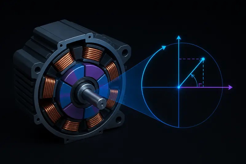
Field-oriented control solves this by changing the reference frame. Instead of three moving sinusoids, it projects the currents into a two-axis frame that rotates in sync with the rotor. In that rotating frame, at constant torque and speed, the current values are constant, not sinusoidal. A plain PI controller can then track a constant setpoint with zero steady-state error. That single reframing is the entire trick behind FOC.
Step 1: Clarke Transform, Three Phases to Two
The Clarke transform converts the three phase currents (Ia, Ib, Ic), which live in a redundant three-axis frame 120 degrees apart, into two orthogonal stationary-frame currents, Ialpha and Ibeta:
Ialpha = Ia
Ibeta  = (Ia + 2*Ib) / sqrt(3)
Because Ia + Ib + Ic = 0 for a balanced three-phase motor, only two phase currents need to be measured in practice; the third is redundant. Ialpha and Ibeta together represent the same current vector as Ia, Ib, Ic, just in a fixed two-dimensional coordinate system attached to the stator instead of three overlapping axes.
Worked Example: Clarke Transform
Suppose at one instant the measured phase currents are:
Ia = 5.0 A
Ib = -6.5 A
Ic = 1.5 A   (redundant check: Ia + Ib + Ic = 0.0, correct)
Applying the Clarke transform:
Ialpha = 5.0
Ibeta  = (5.0 + 2*(-6.5)) / 1.732 = (5.0 - 13.0) / 1.732 = -4.62 A
That is a single fixed vector of magnitude sqrt(5.0^2 + 4.62^2) = 6.81 A, pointing at some angle in the stator frame. It is still rotating over time as the motor spins, which is exactly the problem the next step fixes.
Step 2: Park Transform, Stationary to Rotating Frame
The Park transform rotates the two-axis frame so it spins with the rotor, using the rotor's electrical angle theta_e (the same electrical angle covered in six-step commutation, derived from mechanical angle times pole-pair count):
Id = Ialpha*cos(theta_e) + Ibeta*sin(theta_e)
Iq = -Ialpha*sin(theta_e) + Ibeta*cos(theta_e)
Id is the direct-axis current, aligned with the rotor's magnetic field. Iq is the quadrature-axis current, at 90 electrical degrees to it. Torque in a surface-mount PMSM/BLDC motor is proportional to Iq alone:
Torque = (3/2) * P * lambda_m * Iq
where P is the number of pole pairs and lambda_m is the rotor flux linkage. Id contributes zero torque; its only job is field weakening at high speed. For maximum torque per amp at normal operating speed, FOC deliberately commands Id = 0 and puts all available current into Iq. This is the same 90-degree torque angle target derived from first principles in the six-step commutation article, but here it is held exactly at 90 degrees continuously instead of stepping through six discrete states.
Worked Example: Park Transform
Continuing the example, suppose the rotor's electrical angle at this instant is theta_e = 30 degrees:
cos(30) = 0.866, sin(30) = 0.5

Id = Ialpha*cos(theta_e) + Ibeta*sin(theta_e)
   = 5.0*0.866 + (-4.62)*0.5
   = 4.33 - 2.31
   = 2.02 A

Iq = -Ialpha*sin(theta_e) + Ibeta*cos(theta_e)
   = -5.0*0.5 + (-4.62)*0.866
   = -2.5 - 4.00
   = -6.50 A
Id is not zero here, meaning some current is currently misaligned with the target field angle and producing no torque, just heat. This is exactly what a real FOC current loop corrects on every control cycle.
Step 3: The Current Control Loop
With Id and Iq available, FOC runs two independent PI controllers:
- An Id controller with setpoint 0 A (or a field-weakening value at high speed)
- An Iq controller with setpoint equal to the commanded torque, scaled by the torque constant
Each PI controller outputs a voltage command, Vd and Vq, in the same rotating frame. These get rotated back to the stationary frame with the inverse Park transform, then converted to three-phase voltage commands with the inverse Clarke transform (often combined into Space Vector Modulation, which also improves DC bus utilization by about 15% over simple sinusoidal PWM). The three-phase voltages finally drive the inverter's PWM duty cycles.
Ialpha_cmd = Vd*cos(theta_e) - Vq*sin(theta_e)
Ibeta_cmd  = Vd*sin(theta_e) + Vq*cos(theta_e)
Because this entire loop runs continuously (typically 10 to 20 kHz for the current loop), the current vector is kept locked at 90 degrees to the rotor field at all times, not just at six fixed points per electrical revolution. That is the direct mechanical reason FOC produces smooth, low-ripple torque where six-step commutation produces a rippling one.
What FOC Needs That Six-Step Commutation Does Not
Six-step commutation only needs to know which of six 60-degree sectors the rotor is in, which three cheap hall sensors provide directly. FOC needs the continuous electrical angle, not just a sector, because the Park transform uses sin(theta_e) and cos(theta_e) at every control cycle. Three common ways to get that:
- Quadrature encoder or absolute encoder: gives high-resolution mechanical angle directly; multiply by pole-pair count for electrical angle.
- Sensorless back-EMF or flux observer: estimates angle from the motor's own electrical behavior, but is unreliable at zero and very low speed since there is no back-EMF to observe.
- Hall sensors with interpolation: the same three hall sensors used for six-step commutation give six known angle points per electrical revolution; a common trick is to interpolate between hall edges using a speed estimate, trading some accuracy for using hardware you likely already have.
This is why many practical drives start the motor in six-step mode at zero speed, then switch to FOC once back-EMF becomes usable, or use a hall-interpolation scheme to run FOC across the full speed range with only hall sensors.
Six-Step vs FOC: What Actually Changes
| Property | Six-Step Commutation | Field-Oriented Control |
|---|---|---|
| Current waveform | Stepped, square-ish | Sinusoidal |
| Torque ripple | High, especially at low speed | Low, near-constant torque |
| Angle resolution needed | 6 sectors (60 degrees) | Continuous, sub-degree |
| Audible noise | Noticeable "cogging" hum | Much quieter |
| Computation | Lookup table, trivial | Trig functions + 2 PI loops, real-time |
| Typical use | Fans, low-cost actuators | Robot joints, gimbals, drones, EVs |
Common Implementation Mistake: Wrong Angle Reference
The single most common bug when bringing up FOC on new hardware is an angle offset or scaling error between the sensor's zero position and the motor's actual electrical zero (the point where phase A's back-EMF crosses zero going positive). If that offset is wrong, Id will not sit near zero even under correct current control, current draw will be higher than expected for a given torque, and at large offsets the motor will simply fail to spin or spin with a harsh, jerky motion. This is diagnosed the same way as the direction fault in six-step commutation: log Id, Iq, and theta_e directly, and adjust the angle offset until Id settles near zero at steady-state torque command.
Summary
Field-oriented control is not a different motor topology, it is a different reference frame. The Clarke transform collapses three redundant phase currents into two. The Park transform rotates those two into a frame that spins with the rotor, turning sinusoidal AC quantities into DC quantities a simple PI loop can track with zero steady-state error. Torque comes from Iq alone; Id is held near zero for maximum efficiency. The price is that FOC needs continuous, accurate rotor angle, not just the six-sector information hall sensors give six-step commutation for free.
Building or studying robotics?
Arcbotix publishes practical guides on robotics engineering, control systems and real-world builds. Explore more articles on the blog.