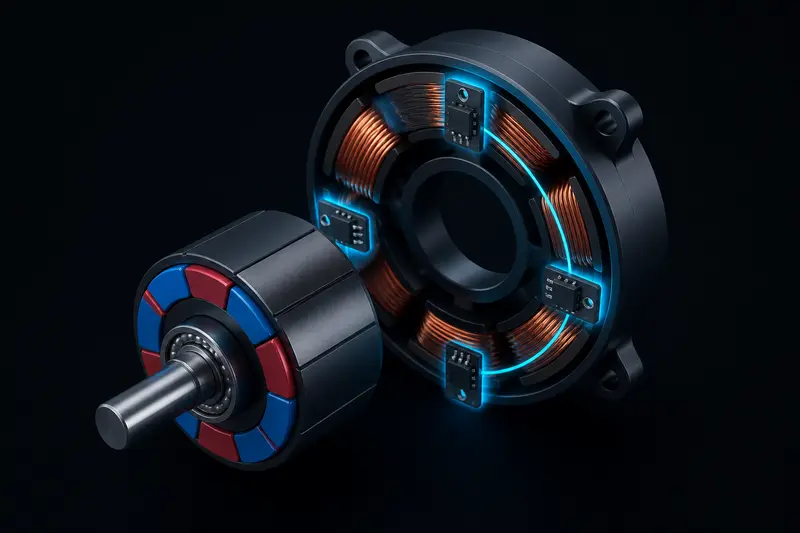
A brushless DC (BLDC) motor has no brushes to mechanically switch current between windings, so something else has to do that job electronically, in sync with the rotor position. The most common low-cost solution is hall sensor commutation: three digital hall-effect sensors report which 60-degree sector the rotor is in, and a lookup table tells the driver which two of the three phases to energize next. This article derives that table from first principles instead of copying one vendor's register settings, so it works on an STM32, an AVR, an ESP32, or anything else with three digital inputs and six PWM-capable outputs.
Why BLDC motors need commutation at all
A BLDC motor is a three-phase motor with a permanent-magnet rotor. To produce continuous torque, the stator's magnetic field has to keep rotating slightly ahead of the rotor's magnetic field, pulling it forward. In a brushed DC motor, a mechanical commutator does this automatically as the shaft turns. In a BLDC motor, the controller must do it electronically, and to do that correctly it needs to know the rotor's approximate position.
Hall sensors solve this cheaply. Three hall-effect sensors are mounted 120 electrical degrees apart around the stator, each one flipping between HIGH and LOW as a rotor magnet pole passes it. Because there are three sensors with two states each, but only six of the eight possible combinations occur during a real rotation (000 and 111 never happen with correctly spaced sensors), you get exactly six valid states per electrical revolution, each spanning 60 electrical degrees. That is why this scheme is called six-step commutation.
Electrical degrees vs mechanical degrees
Before building the table, separate two related but different quantities. Electrical degrees describe one cycle of the stator's rotating field; mechanical degrees describe the actual shaft rotation. They are related by the motor's pole-pair count P:
electrical_degrees = mechanical_degrees * PA common hobby outrunner BLDC has 7 pole pairs (14 magnet poles). One full mechanical revolution (360 mechanical degrees) then corresponds to 7 full electrical cycles, or 2520 electrical degrees. Each of the six hall states still only covers 60 electrical degrees, which for this motor is 360 / 7 ≈ 51.4 mechanical degrees. This matters if you ever try to convert hall state changes into a shaft angle or a speed estimate: six hall transitions gets you one electrical cycle, not one mechanical revolution.
The 90-degree torque angle target
Torque in a BLDC motor is maximized when the stator's field vector leads the rotor's field vector by 90 electrical degrees. Six-step commutation can only approximate this because it switches the energized phase pair only six times per electrical cycle, so the torque angle actually swings between 60 and 120 degrees around that 90-degree target, then resets at each hall transition. This is the source of the torque ripple that six-step (trapezoidal) commutation is known for, compared to sinusoidal field-oriented control. For most robot joints driven through a gearbox, that ripple is smoothed out mechanically and is not worth the added complexity of FOC. See servo vs stepper vs BLDC motor selection for when that tradeoff is worth making at all.
Deriving the six-step table
Label the three stator phases A, B, and C, and the three hall sensors H1, H2, and H3, mounted so each one leads the next by 120 electrical degrees. As the rotor turns, the hall states cycle through six combinations in a fixed order. At each state, exactly one phase is driven high (current source), one is driven low (current sink), and one is left floating (high-impedance), so current flows through two of the three windings at a time.
The standard clockwise-rotation table looks like this. Treat it as a starting point to verify against your own motor, not a universal constant, since a manufacturer's hall wiring and phase labeling can shift which physical state maps to which row:
| Hall state (H1 H2 H3) | Sector | Phase A | Phase B | Phase C |
|---|---|---|---|---|
| 001 | 1 | PWM (high) | GND (low) | Float |
| 011 | 2 | PWM (high) | Float | GND (low) |
| 010 | 3 | Float | PWM (high) | GND (low) |
| 110 | 4 | GND (low) | PWM (high) | Float |
| 100 | 5 | GND (low) | Float | PWM (high) |
| 101 | 6 | Float | GND (low) | PWM (high) |
Reversing direction is simply a matter of reading the table in the opposite row order (or equivalently, swapping any two of the three phase wires, which is the quick hardware fix people reach for during bring-up).
Portable commutation code
The table above maps directly onto an array indexed by the 3-bit hall reading. This version is deliberately hardware-agnostic: set_phase() is the only function you need to reimplement per microcontroller, wiring it to whatever PWM/GPIO API your platform provides.
typedef enum { PHASE_PWM_HIGH, PHASE_GND_LOW, PHASE_FLOAT } phase_state_t;

typedef struct {
    phase_state_t a, b, c;
} commutation_step_t;

// Indexed by hall reading (H1<<2 | H2<<1 | H3). Unused indices (0b000, 0b111)
// should never occur with correctly spaced sensors; treat them as a fault.
static const commutation_step_t COMMUTATION_TABLE[8] = {
    /* 000 */ {PHASE_FLOAT, PHASE_FLOAT, PHASE_FLOAT},   // invalid
    /* 001 */ {PHASE_PWM_HIGH, PHASE_GND_LOW, PHASE_FLOAT},
    /* 010 */ {PHASE_FLOAT, PHASE_PWM_HIGH, PHASE_GND_LOW},
    /* 011 */ {PHASE_PWM_HIGH, PHASE_FLOAT, PHASE_GND_LOW},
    /* 100 */ {PHASE_GND_LOW, PHASE_FLOAT, PHASE_PWM_HIGH},
    /* 101 */ {PHASE_FLOAT, PHASE_GND_LOW, PHASE_PWM_HIGH},
    /* 110 */ {PHASE_GND_LOW, PHASE_PWM_HIGH, PHASE_FLOAT},
    /* 111 */ {PHASE_FLOAT, PHASE_FLOAT, PHASE_FLOAT},   // invalid
};

void commutate(uint8_t hall_reading, uint16_t pwm_duty) {
    if (hall_reading == 0 || hall_reading == 7) {
        fault_stop();  // sensor wiring fault or motor not turning
        return;
    }
    commutation_step_t step = COMMUTATION_TABLE[hall_reading];
    set_phase(PHASE_A, step.a, pwm_duty);
    set_phase(PHASE_B, step.b, pwm_duty);
    set_phase(PHASE_C, step.c, pwm_duty);
}
Call commutate() from a hall-change interrupt (edge-triggered on all three hall GPIOs) rather than polling in the main loop. At a few thousand RPM with a 7-pole-pair motor, hall transitions arrive fast enough that even a few hundred microseconds of polling latency introduces a noticeable torque angle error. This is the same reason a tight motor control loop deserves its own interrupt context rather than sharing a slow main loop with other work, similar to the cascaded current/velocity/position loop structure used for closed-loop torque control.
The classic wrong-direction and stall symptom
The single most common bring-up bug with sensored BLDC commutation is a motor that either spins the wrong direction, or worse, judders and stalls under load without turning smoothly at all. Both symptoms usually trace back to the same root cause: the hall sensor wiring does not match the assumed phase order that the commutation table was derived for. If two hall wires are swapped relative to the phase wiring, the controller ends up energizing the wrong phase pair for the rotor's actual position, which can still produce enough torque to twitch the shaft but pulls it in inconsistent directions as it turns, rather than smoothly forward.
To diagnose it: with the motor unpowered, rotate the shaft by hand and log the raw 3-bit hall reading. You should see exactly six distinct values, each one differing from its neighbor by a single bit, cycling in a consistent order as you turn the shaft one direction. If a state repeats, skips, or two bits change at once between adjacent readings, a hall sensor is either wired wrong or physically misaligned. If the six states are clean but the motor still runs backward or stalls, swap any two motor phase leads (not hall leads) and retest; that reverses the effective phase order without needing to touch the table itself.
When to reach for FOC instead
Six-step hall commutation is the right starting point for most hobby and small-robot BLDC joints: it needs only cheap digital hall sensors, integer-only math, and a simple lookup table. It falls short when you need very smooth low-speed torque (six discrete steps per electrical cycle create noticeable cogging at low RPM), maximum efficiency, or silent operation, all of which sinusoidal field-oriented control handles better at the cost of needing continuous rotor angle (from an encoder or sensorless back-EMF estimation) and real-time Park/Clarke transform math. For a first BLDC joint controller, get six-step commutation working and verified before considering that jump.
Building or studying robotics?
Arcbotix publishes practical guides on robotics engineering, control systems and real-world builds. Explore more articles on the blog.