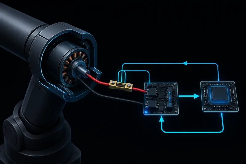
If you have already wired up a shunt resistor or an inline current sensor on a robot joint's motor line, you know how to get a current reading. What is far less documented is what to do with that number. Torque control for robot arm joints means turning a measured current into a commanded torque, closing a fast inner loop around it, and using that loop as the foundation for velocity and position control above it. This article walks through the actual math and a worked tuning example, not just the concept.
Why torque control for robot arm joints matters
A position controller alone does not know how hard a joint is pushing. If a gripper contacts an object, or a joint jams against a mechanical stop, a pure position loop keeps increasing its output trying to close a position error that physically cannot close. The result is excessive force, a stalled motor dumping full current as heat, or a broken part. A torque-aware inner loop caps how much force each joint is allowed to apply, independent of what the outer position loop is asking for.
This matters for three concrete situations on a robot arm: contact tasks (inserting a part, pressing a button), collision safety (stopping before damaging the joint or gearbox), and smooth low-speed motion where friction and cogging would otherwise make position control jerky.
From current to torque: the Kt constant
For a brushed DC motor or a BLDC motor driven with field-oriented control, output torque is approximately proportional to the current in the torque-producing axis:
tau_motor = Kt * I
where Kt is the motor's torque constant in newton-meters per amp, and I is the measured current (for BLDC, this is the quadrature-axis current, Iq, not the raw phase current). Motor datasheets list Kt directly, often as "torque constant" or derived from the back-EMF constant Ke (in SI units, Kt and Ke are numerically equal).
Worked example: a small joint uses a BLDC motor with Kt = 0.06 Nm/A, driving a 50:1 harmonic drive at 90% efficiency. If the current sensor reads 3.2 A of Iq:
tau_motor = 0.06 * 3.2 = 0.192 Nm
tau_joint = tau_motor * 50 * 0.90 = 8.64 Nm
That joint-side torque number is what you actually want to control and limit, since it is what the arm exerts on the world. Always apply the gearbox ratio and efficiency after the Kt calculation, not before, or your torque limits will be off by the reduction ratio.
The cascaded control structure
Industrial and research robot arm joints almost universally use a cascade of three nested loops, each running at a different rate:
- Current loop (innermost, fastest, typically 10-20 kHz): takes a commanded current (or torque) as its setpoint and drives the motor's actual current to match, using the current sensor as feedback.
- Velocity loop (middle, typically 1-2 kHz): takes a commanded velocity, computes a current command to achieve it, using encoder-derived velocity as feedback.
- Position loop (outermost, slowest, typically 100-500 Hz): takes a commanded position (from a trajectory planner), computes a velocity command, using encoder position as feedback.
Each outer loop's output becomes the next inner loop's setpoint. The key property this gives you: since torque is proportional to current, a torque limit is simply a clamp on the current command coming out of the velocity loop, before it reaches the current loop. This is where state-space approaches like LQR can also be used for the velocity or position loop instead of PID, but the current loop itself is almost always a simple PI controller because the motor electrical dynamics are close to a first-order system.
Tuning the current loop: a worked example
The current loop controls motor current by adjusting applied voltage, working against the motor's electrical time constant. Model the motor electrically as a series resistance R and inductance L:
L * dI/dt + R * I = V - Ke * omega
For current-loop tuning, the back-EMF term (Ke * omega) is treated as a slow-moving disturbance rather than part of the plant, since the current loop runs much faster than the mechanical dynamics. This leaves a first-order electrical plant with time constant:
tau_e = L / R
Worked numbers: motor winding resistance R = 0.4 ohm, inductance L = 0.2 mH. Electrical time constant:
tau_e = 0.0002 / 0.4 = 0.5 ms
A standard approach is pole-zero cancellation: choose the PI controller's zero to cancel the plant pole, then pick the loop bandwidth. For a PI controller with gains Kp and Ki, the zero is at Kp/Ki. Setting Kp/Ki = L/R cancels the electrical pole, leaving a first-order closed loop with time constant L/Kp. If you want a closed-loop current-loop bandwidth of 2 kHz (angular frequency omega_c = 2*pi*2000 = 12566 rad/s):
Kp = L * omega_c = 0.0002 * 12566 = 2.51 V/A
Ki = Kp * R / L = 2.51 * 0.4 / 0.0002 = 5021 V/(A*s)
In discrete form at a 20 kHz control rate (dt = 50 microseconds), the incremental PI update is:
error = I_command - I_measured
integral += error * dt
V_command = Kp * error + Ki * integral
V_command = clamp(V_command, -V_bus, V_bus)
Sanity check the bandwidth choice against your PWM switching frequency: a current loop bandwidth should generally stay at or below one-tenth of the PWM frequency to avoid instability from the sampling and switching delay. At a 20 kHz PWM rate, a 2 kHz current loop bandwidth is a safe margin.
Implementing a torque limit
With Kt known and the current loop tuned, a torque limit becomes a straightforward clamp applied to whatever current command the outer velocity loop produces:
I_command_raw = velocity_loop_output(velocity_error)
I_max = torque_limit_joint / (Kt * gear_ratio * gear_efficiency)
I_command = clamp(I_command_raw, -I_max, I_max)
For the earlier example (Kt = 0.06 Nm/A, gear_ratio = 50, efficiency = 0.90), a joint-level torque limit of 6 Nm translates to a current limit of:
I_max = 6 / (0.06 * 50 * 0.90) = 2.22 A
Any velocity-loop output demanding more current than this gets clamped, so the joint physically cannot exceed 6 Nm of output torque regardless of position or velocity error. This is the mechanism behind collision-stop behavior and compliant, force-limited motion on modern robot arms.
Common mistakes
- Using raw phase current instead of Iq for BLDC motors. Only the quadrature-axis current after Park/Clarke transforms is proportional to torque; raw phase current oscillates with rotor position and does not give a stable torque estimate.
- Ignoring gearbox efficiency in the torque limit calculation. Efficiency of 85-95% for a harmonic drive or planetary gearbox is not negligible when setting a safety-critical torque limit; a 10% error there is a 10% error in the actual force the joint can apply before it should stop.
- Setting the current loop bandwidth too close to the PWM frequency. This is a common source of high-frequency current oscillation ("current loop ringing") that looks like a tuning problem but is actually a sample-rate problem.
- Skipping the inner current loop entirely and commanding voltage directly from a position PID. This works at low performance requirements but gives you no way to enforce a torque limit, since voltage does not map cleanly to torque once back-EMF and load vary.
Conclusion
Torque control for robot arm joints is not a separate control paradigm from position or velocity control, it is what sits underneath both once you close a current loop around the motor and use the Kt relationship to translate between amps and newton-meters. The practical payoff is a clean, physically meaningful torque limit you can enforce in software, which is the basis for safe contact tasks and collision response on a real arm. For the full nested structure, including how to size the velocity and position loop gains on top of this current loop with a bandwidth-separation rule, see the cascaded PID control article.
Building or studying robotics?
Arcbotix publishes practical guides on robotics engineering, control systems and real-world builds. Explore more articles on the blog.