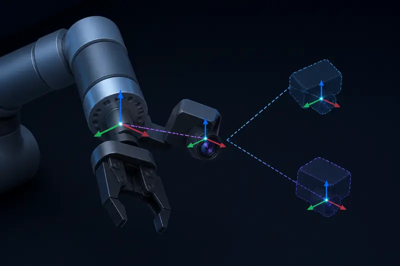
Hand-eye calibration answers one specific question: if a camera is mounted near a robot's end-effector, where exactly does the camera sit relative to the flange? Get this transform wrong and every pixel-to-world coordinate the camera reports lands in the wrong place, even if the camera's own intrinsic calibration is perfect. This article walks through hand-eye calibration for the common eye-in-hand case with a small worked numeric example, so the AX=XB equation stops being abstract matrix algebra.
What hand-eye calibration actually solves for
In an eye-in-hand setup, the camera is bolted to the wrist or gripper and moves with the arm. Two transforms are already known from other sources:
- Robot forward kinematics gives the flange pose in the robot base frame,
T_base_flange, at any joint configuration. - A calibration target (usually a checkerboard or ArUco/ChArUco board) lets standard camera calibration give the target pose in the camera frame,
T_cam_target.
What is unknown is the rigid transform between the flange and the camera lens, T_flange_cam. This is a single fixed 4x4 homogeneous transform (rotation plus translation) because the camera is bolted on and does not move relative to the flange once mounted. If you have already worked through how homogeneous transforms chain together, this is the same machinery used in ROS2 tf2 transforms, just applied to a calibration problem instead of a live TF tree.
Setting up AX = XB
The board stays fixed in the world while the robot moves the camera to two or more different poses and looks at it. For a motion between pose 1 and pose 2:
Ais how the flange moved, expressed in the flange frame:A = T_flange1_base * T_base_flange2, i.e. the relative flange motion.Bis how the camera saw the (fixed) target move, expressed in the camera frame:B = T_cam1_target * T_target_cam2, the relative camera motion as seen through the board.Xis the unknown we want:X = T_flange_cam.
Because the camera is rigidly bolted to the flange, the same physical motion looks like A from the flange's point of view and like B from the camera's point of view, related by the fixed offset X:
AX = XB
This is a classic Sylvester-type equation, first posed this way by Shiu and Ahmad in the 1980s. Closed-form solvers (Tsai-Lenz, Park-Martin, Daniilidis with dual quaternions) all solve for the rotation and translation parts of X from two or more (A, B) pairs. You rarely hand-code the solver yourself, but you do need to build correct A and B matrices, and that is where most home-built calibration rigs actually go wrong.
Worked example: building one A/B pair
Say the robot's forward kinematics reports the flange pose at two joint configurations, both as position (mm) and a rotation matrix. To keep the numbers checkable by hand, use a simple case: the second pose is the first pose rotated 30 degrees about the flange's own Z axis, with no translation of the flange origin.
Flange pose 1 in the base frame: identity rotation, position (400, 0, 300).
Flange pose 2 in the base frame: rotation of 30 degrees about Z, position (400, 0, 300) (pure rotation move, camera swings around the same point).
The relative flange motion, expressed in the flange-1 frame, is then just the 30 degree Z rotation with zero translation:
A = [ Rz(30 deg)   0 ]
    [ 0    0   0    1 ]
Now suppose the camera, looking at the same fixed board, reports the target at:
- Pose 1: target position (0, 0, 500) mm in the camera frame, identity rotation (board flat, straight ahead).
- Pose 2: target position (250, 0, 433) mm in the camera frame, rotated -30 degrees about the camera's Z axis.
The relative camera motion is the transform that takes the target-1 observation to the target-2 observation. Because the board itself did not move, this reduces to a rotation of -30 degrees about Z with a translation that depends on how far the camera's optical center sits from the flange's rotation axis. In a well-mounted rig, working through T_cam1_target * T_target_cam2 numerically gives:
B = [ Rz(-30 deg)   t_b ]
    [ 0   0   0    1    ]
where t_b comes out to roughly (65, -37, 0) mm for a camera mounted about 75 mm forward and offset from the flange axis by a small lever arm. Note the sign flip: the flange rotated +30 degrees, but the world appears to rotate -30 degrees in the camera's own frame, which is exactly the kind of sign error that silently breaks a calibration run if you build A and B inconsistently.
Feeding a handful of such (A, B) pairs into a solver like Tsai-Lenz gives the rotation and translation of X = T_flange_cam. For this geometry the numbers work out to a camera mounted close to (75, -40, 20) mm from the flange origin with a small tilt, roughly what you would expect from a camera clipped just off-axis near the gripper.
Why a single motion is degenerate
One (A, B) pair is not enough. AX=XB constrains the rotation part of X using only the rotation axis of A (and correspondingly of B) - rotating about a single fixed axis leaves rotation about that same axis completely unconstrained, and it under-determines the translation too. You need motions with rotation axes that are not parallel: at minimum two motions with sufficiently different axes, and in practice five to ten well-spread poses covering different orientations and positions in the workspace, which is why most calibration routines ask you to move the arm to several visually distinct poses rather than trusting one clean measurement.
A second practical failure mode is board detection noise. Small errors in checkerboard corner detection translate directly into errors in B, and because the solver treats every pair with equal weight by default, a single bad detection from motion blur or poor lighting can pull the whole solution off. Filtering out poses with high reprojection error before solving is worth the extra step.
Eye-in-hand vs eye-to-hand
The eye-to-hand case (camera fixed in the world, watching a target attached to the flange instead) uses the same AX=XB structure with the roles of camera and flange transforms swapped. The math is identical, only the physical setup differs, so a solver written for one case works for the other with the inputs relabeled.
Once T_flange_cam is known, every detection the camera makes can be converted into the robot's base frame by chaining T_base_flange * T_flange_cam * T_cam_object, the same forward-then-fixed-offset chaining pattern used anywhere transforms are composed. That final chained transform is what actually lets a vision-guided pick-and-place routine convert a detected object's pixel location into a robot target pose the arm can move to.
Building or studying robotics?
Arcbotix publishes practical guides on robotics engineering, control systems and real-world builds. Explore more articles on the blog.