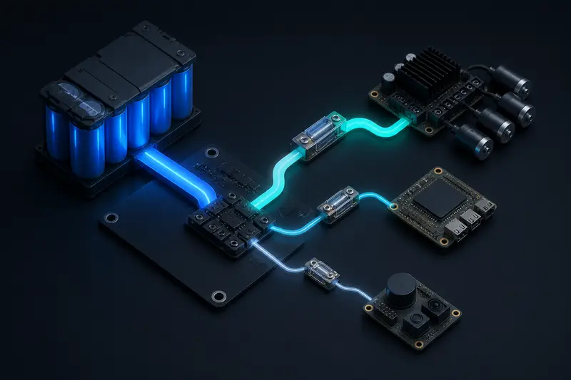
Power budgeting for mobile robots is usually explained as "list your components, add up the current, add margin." That advice is not wrong, but it skips the two steps that actually determine whether your robot works reliably: separating peak current from average current, and using the resulting numbers to size your wiring and fusing, not just your battery. A robot that browns out its main compute board every time the drive motors stall against an obstacle has a wiring problem, not a battery problem, and no amount of extra battery capacity fixes it.
This guide walks through building a real power budget for a mobile robot: listing components with both average and peak current, summing them correctly, sizing battery capacity and discharge rate, and then carrying those numbers through to wire gauge and fuse selection.
Step 1: Build a Component Current Table
Start by listing every current-drawing subsystem on the robot, with two numbers for each: typical average current during normal operation, and peak current during the worst case that subsystem will actually hit. Peak is not a vague safety margin, it is a specific physical event: motor stall current, sensor power-on inrush, or a compute board's brief current spike under full CPU/GPU load.
| Component | Typical Average | Peak | Peak Cause |
|---|---|---|---|
| 2x drive motors (12V DC gear motors) | 3.0 A total | 14.0 A total | Stall against an obstacle |
| Compute board (SBC + small GPU) | 2.5 A | 4.0 A | Full CPU/GPU load burst |
| 2D LiDAR | 0.4 A | 0.9 A | Motor spin-up on power-on |
| IMU + microcontroller | 0.2 A | 0.3 A | Negligible, listed for completeness |
| Wi-Fi / comms module | 0.3 A | 0.8 A | Transmit burst |
Get motor stall current from the motor's datasheet, not the running current, since a wheel jammed against a curb or a leg pinned mid-stride draws several times its normal current for as long as the stall lasts. If a datasheet number is not available, measure it directly: hold the motor shaft stationary with a bench supply and current meter in line, for a few seconds only, to avoid overheating the winding.
Step 2: Sum Average and Peak Separately
Two sums matter, and they answer two different questions. Average current, summed across every component's typical draw, tells you how long the battery will last. Worst-case peak current, summed as if every component hit its peak at the same instant, tells you what the battery, main fuse, and main wiring harness must survive without sagging or tripping.
I_avg  = 3.0 + 2.5 + 0.4 + 0.2 + 0.3 = 6.4 A
I_peak = 14.0 + 4.0 + 0.9 + 0.3 + 0.8 = 20.0 A
Treating every component's peak as simultaneous is deliberately conservative. In practice a LiDAR spin-up rarely coincides exactly with a motor stall, but sizing the main harness and fuse for the simultaneous worst case is cheap insurance against an intermittent brownout that is painful to debug later. If you have telemetry from a working prototype, you can refine this with a logged peak instead of the summed worst case, but do that only after the first build has run long enough to trust the log.
Step 3: Size Battery Capacity and Discharge Rate
Capacity follows from average current and your runtime target, with a usable-fraction correction since you should not fully discharge most rechargeable chemistries in normal use:
Capacity (Ah) = I_avg x Target Runtime (h) / Usable FractionFor the robot above with a 6.4 A average draw and a 90-minute runtime target, using an 80 percent usable fraction typical for LiPo:
Capacity = 6.4 x 1.5 / 0.8 = 12.0 AhDischarge rate is a separate check against the peak sum, not the average. A pack's maximum current is its C-rating multiplied by capacity:
Max Current (A) = C-rating x Capacity (Ah)A 12Ah pack needs at least a 20A/12Ah = 1.7C rating to cover the 20A peak without voltage sag, but most off-the-shelf packs are rated well above the minimum, so a 5C to 10C pack gives real headroom rather than running at the edge of its rating on every stall event.
Step 4: Translate the Budget into Wire Gauge
Once you know the peak current each branch of the harness must carry, wire gauge follows from standard ampacity tables, not guesswork. For short robot wiring runs (under about 1 meter) with a small allowance above continuous-duty ratings, common choices are:
- 22 AWG: up to about 3 A, fine for the IMU/microcontroller branch.
- 18 AWG: up to about 7 A, adequate for the compute board and comms branches.
- 14 AWG: up to about 15 A, needed for a single drive motor's stall current.
- 12 AWG or heavier: for the main battery-to-distribution-board harness, which must carry the full 20A peak sum from Step 2.
Undersized wire does not fail cleanly, it heats up and drops voltage under load, which shows up as an intermittent brownout on whatever component shares that rail, exactly the kind of bug that is hard to reproduce on a bench where you are not stalling a motor against a curb. Size the main harness for the worst-case peak sum, and size each branch for that branch's own peak, not the whole robot's average.
Step 5: Size the Main Fuse or Breaker
The main fuse protects the wiring, not the battery, so it should be rated above your worst-case peak sum but below the wire's ampacity. For the 20A peak sum on 12 AWG wire (rated around 20 to 25A for a short run), a 25A fast-blow fuse is a reasonable choice: it will not nuisance-trip on a normal stall event but will still open before the wire insulation is damaged by a genuine short circuit.
Branch-level fusing or resettable polyfuses on individual subsystems (compute board, sensor rail) are worth adding on top of the main fuse, since a single main fuse sized for the whole robot will not protect an 18 AWG sensor branch from a short on that branch specifically, it will just let the wire on that branch overheat before the main fuse ever sees enough current to open.
A Note on Actuator Choice
The peak current numbers in Step 1 depend heavily on which actuators you picked in the first place. A stepper motor draws its rated current continuously, even while holding position at zero speed, which changes the average sum more than the peak sum, while a BLDC motor's ESC needs current ratings sized for peak acceleration current that can be several times its steady-state draw. See servo vs stepper vs BLDC motor for robotics for how actuator type shapes the current profile you are budgeting for in the first place.
The most common power budgeting mistake is sizing the battery for average draw and stopping there. The battery, the main harness, and the main fuse each need to survive the worst-case peak, not the typical case, or the first hard stall event becomes an intermittent brownout that is much harder to debug than a budget mistake caught on paper.
Conclusion
A real power budget for a mobile robot has two separate sums, average current for runtime and battery capacity, and worst-case peak current for the main harness, fuse, and discharge-rate check. Build the component table with both numbers, size the battery from the average, then size wire gauge and fusing from the peak, branch by branch. Skipping the peak-vs-average split is why a robot can pass a bench test on a regulated supply and still brown out in the field the first time a wheel catches on something.
Building or studying robotics?
Arcbotix publishes practical guides on robotics engineering, control systems and real-world builds. Explore more articles on the blog.