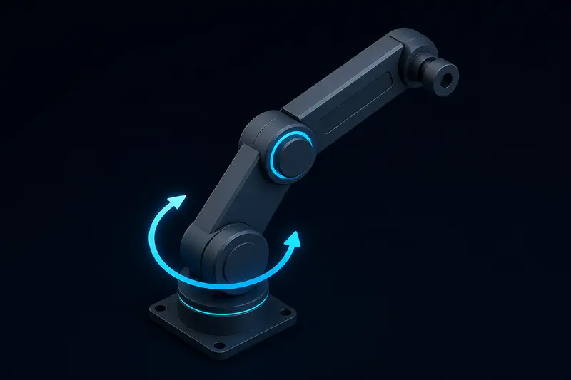
If a robot arm joint sags when you cut power to the motor, or the arm holds a shaky position that drifts downward under load, the position loop is fighting gravity every cycle instead of getting help from a feedforward term. Robot arm gravity compensation is that missing term: a torque command computed directly from the arm's mass, link geometry, and current joint angle, added on top of whatever the PD or PID position loop is already doing. This article derives the formula for a single link, extends it to a two-link arm, and works through actual numbers so you can check your own implementation against a known-good answer.
What gravity compensation actually is
A robot joint's motor has to produce two different kinds of torque at once. One part corrects position error, the job of the PD or PID loop. The other part simply holds the arm up against gravity, which does not go away even when the position error is zero. If you only run a PD loop, the proportional term has to build up a nonzero steady-state error before it generates enough torque to hold the arm up, which is exactly the sag you see in an undercompensated joint.
Gravity compensation separates that second job into its own feedforward term, computed from a physical model instead of from error:
tau_total = tau_pd + tau_gravity
tau_pd = Kp * (theta_desired - theta) - Kd * theta_dot
tau_gravity = g(theta)
Because tau_gravity is computed directly from the current angle rather than from an error signal, it responds instantly and does not depend on the PD gains. The PD loop is then only responsible for correcting small disturbances and following trajectories, which lets you run much lower gains without sag or oscillation.
Deriving the torque for a single link
Consider one rigid link, length l, with its center of mass at the link's midpoint (a common simplification for a roughly uniform link). The link rotates about a horizontal joint axis, with theta measured from horizontal (theta = 0 means the link points straight out horizontally, theta = 90 degrees means it points straight up).
The gravitational torque about the joint is the weight of the link times the horizontal distance from the joint axis to the center of mass:
tau_gravity = m * g * (l / 2) * cos(theta)where m is the link mass in kg, g is 9.81 m/s^2, l is the link length in meters, and l / 2 is the distance to the center of mass. The cosine term matters: torque is maximum when the link is horizontal (cos(0) = 1, full moment arm) and zero when the link points straight up or straight down (cos(90) = 0, no moment arm, gravity pulls straight through the joint axis).
Worked example: a link with mass 1.2 kg, length 0.30 m, held at theta = 30 degrees above horizontal.
tau_gravity = 1.2 * 9.81 * (0.30 / 2) * cos(30 deg)
            = 1.2 * 9.81 * 0.15 * 0.866
            = 1.529 N*m
That 1.529 N*m is the torque the motor must supply just to hold the link at 30 degrees, before the PD loop does anything at all. If your gearbox and motor combination cannot sustain that continuously (check the motor's rated continuous torque, not peak), the joint will sag no matter how you tune the PD gains, because you are asking the position loop to compensate for an actuator that is undersized for the static load.
Extending to a two-link arm
A two-link arm is more representative of a real robot joint, and it introduces an important detail: the gravity torque at the shoulder joint depends on both link angles, because the shoulder has to support the weight of the entire forearm as well as its own link.
Define theta1 as the shoulder angle from horizontal and theta2 as the elbow angle relative to the upper arm. Let link 1 (upper arm) have mass m1 and length l1, and link 2 (forearm) have mass m2 and length l2. The gravity torque at each joint is:
tau_g1 = (m1 * (l1/2) + m2 * l1) * g * cos(theta1)
         + m2 * (l2/2) * g * cos(theta1 + theta2)

tau_g2 = m2 * (l2/2) * g * cos(theta1 + theta2)
The elbow's gravity torque, tau_g2, only depends on the combined angle theta1 + theta2, since the forearm's orientation relative to gravity is what matters, not the shoulder angle alone. The shoulder's torque, tau_g1, has to carry both its own link's weight and the forearm's full weight acting at the far end of the upper arm (hence the m2 * l1 term, not m2 * l1/2: the forearm's mass acts through the elbow joint, a full link-length away from the shoulder).
Worked numeric example: m1 = 1.5 kg, l1 = 0.25 m, m2 = 0.8 kg, l2 = 0.20 m, with theta1 = 45 deg and theta2 = -30 deg (elbow bent back 30 degrees from straight).
theta1 + theta2 = 15 deg

tau_g1 = (1.5 * 0.125 + 0.8 * 0.25) * 9.81 * cos(45 deg)
         + 0.8 * 0.10 * 9.81 * cos(15 deg)
       = (0.1875 + 0.20) * 9.81 * 0.7071
         + 0.7848 * 0.9659
       = 0.3875 * 9.81 * 0.7071 + 0.7580
       = 2.688 + 0.758
       = 3.446 N*m

tau_g2 = 0.8 * 0.10 * 9.81 * cos(15 deg)
       = 0.7848 * 0.9659
       = 0.758 N*m
Notice the shoulder needs more than four times the elbow's torque here, which is typical: the shoulder motor and gearbox on a real arm are almost always sized larger than the elbow's for exactly this reason.
Implementing it as feedforward code
The structure below runs the gravity model every control cycle and adds it directly to the PD output before sending the command to the motor driver. This assumes you already have a joint torque control loop in place, see torque control for robot arm joints for how a torque command gets turned into a current command at the motor.
import math

G = 9.81

def gravity_torque_two_link(m1, l1, m2, l2, theta1, theta2):
    tau_g1 = (m1 * (l1 / 2) + m2 * l1) * G * math.cos(theta1) \
             + m2 * (l2 / 2) * G * math.cos(theta1 + theta2)
    tau_g2 = m2 * (l2 / 2) * G * math.cos(theta1 + theta2)
    return tau_g1, tau_g2

def control_step(theta1, theta2, theta1_dot, theta2_dot,
                  theta1_desired, theta2_desired, Kp, Kd):
    tau_g1, tau_g2 = gravity_torque_two_link(
        m1=1.5, l1=0.25, m2=0.8, l2=0.20,
        theta1=theta1, theta2=theta2)

    tau_pd1 = Kp * (theta1_desired - theta1) - Kd * theta1_dot
    tau_pd2 = Kp * (theta2_desired - theta2) - Kd * theta2_dot

    tau1 = tau_pd1 + tau_g1
    tau2 = tau_pd2 + tau_g2
    return tau1, tau2
A few practical points that matter more than the formula itself:
- Update the gravity term at your full control loop rate (100 Hz or higher for a smooth-moving arm), not once per trajectory waypoint. The joint angle changes continuously, and a stale gravity estimate reintroduces the sag you were trying to remove.
- Once gravity feedforward is doing its job, you can usually lower
KpandKdsignificantly, since the PD loop is no longer being asked to fight a constant static load. Lower gains mean less audible motor buzz and less sensitivity to encoder noise. - The center-of-mass-at-midpoint assumption is a simplification. If a link carries a payload, a battery, or a heavier motor at one end, measure or estimate the true center of mass and moment arm rather than assuming the geometric midpoint, or the compensation will be systematically off in one direction.
- Gravity compensation only cancels the static, position-dependent load. It does not replace a velocity/acceleration feedforward term for fast trajectories, and it does not account for friction. Those are separate additive terms, not something the gravity model should be stretched to cover.
Diagnosing an undercompensated joint
Two symptoms point specifically at a missing or wrong gravity term rather than a bad PD tune:
- The arm sags to a lower angle at rest and only creeps back under integral action, or oscillates around the target if there is no integral term. This is the direct signature of the PD loop needing a nonzero steady-state error to generate holding torque.
- The required PD gains change depending on the arm's pose. If a gain set that works well with the arm horizontal causes overshoot or buzz with the arm vertical, that is gravity load changing with position, not a badly tuned controller. Adding the feedforward term should make one gain set work well across the full range of motion.
If you already have a working position loop and see either symptom, add the gravity term first before touching Kp or Kd again. It is a common mistake to keep raising gains to fight a static load that a two-line formula would have cancelled directly.
Building or studying robotics?
Arcbotix publishes practical guides on robotics engineering, control systems and real-world builds. Explore more articles on the blog.