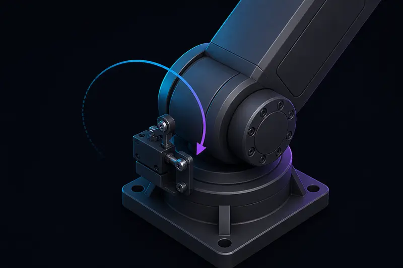
An incremental encoder only counts pulses. It has no idea what angle the joint is actually at until you tell it. Every time you power off a robot arm, that count resets to zero at whatever position the joint happens to be sitting in, not at the joint's true zero position. Homing is the routine that fixes this: it moves the joint to a physical reference point, usually a limit switch, and uses that trigger point to compute the offset between the raw encoder count and the joint's real-world angle.
Get the homing sequence and the offset math right and the joint lands within a fraction of a degree of the same position every single startup. Get it wrong and you get a joint that homes to a slightly different angle each time, drifting worse the faster it approaches the switch.
Why robot joints need homing
Two encoder types show up in robot joints: absolute and incremental. An absolute encoder reports a unique angle immediately at power-up, so it never needs homing. An incremental (quadrature) encoder only reports relative motion, counting up or down as the shaft turns, so the controller has to establish where zero actually is every time the system powers on. Incremental encoders are far more common on hobbyist and mid-size robot arms because they are cheaper and simpler to wire, which is exactly why homing shows up as a recurring build step.
A limit switch is the simplest way to give an incremental joint a fixed physical reference: a mechanical microswitch, an optical interrupter, or a Hall-effect sensor mounted so that a flag or cam on the joint trips it at one specific angle.
Where to mount the switch
Mount the switch so it triggers at, or just past, one mechanical end of the joint's travel, not in the middle of the working range. If it trips mid-range, the homing routine has to know which direction to search, which adds ambiguity. At an end-of-travel position there is only one direction to approach from.
Also decide whether the switch is on the motor side or the output side of the gearbox. If it is on the output side (after the reduction), one trigger event maps directly to one joint angle, which is what you want. If it is on the motor side, a single trigger only tells you the motor shaft position modulo one output-shaft revolution, and you need extra logic (like a known start position) to resolve which output revolution you are actually in. For any joint with more than one output revolution of travel per limit switch trigger, mount the switch on the output side or use an absolute encoder with a single-turn range that covers the joint's motion.
The homing sequence
A repeatable homing routine has three phases, not one:
- Fast approach. Move the joint toward the switch at moderate speed until it trips. This gets you close quickly but not precisely, because switch trigger points shift slightly with approach speed due to debounce filtering and mechanical overtravel.
- Back off. Reverse a small, fixed distance (typically a few degrees of joint travel) until the switch releases.
- Slow re-approach. Move forward again at low speed until the switch trips a second time. Latch the encoder count at this exact trigger point.
The slow re-approach is the step builders skip, and it is the one that makes homing repeatable. Approaching fast means the joint travels further between the controller's poll of the switch state and the actual mechanical trigger, so the logged count varies with speed and even with battery voltage sag. Approaching slowly, after already being close from the back-off step, minimizes that overtravel and gives a consistent trigger count run to run.
Worked example: from trigger count to home offset
Take a joint with a quadrature encoder rated at 4096 counts per revolution (CPR) mounted on the motor shaft, driving a 100:1 gearbox, with the limit switch mounted on the output side so one trigger corresponds to one specific joint angle. See our encoder resolution guide for how CPR and gear ratio combine into output-shaft resolution.
Output-shaft counts per revolution:
4096 CPR × 100 (gear ratio) = 409,600 counts per output revolution
Resolution at the joint: 360° / 409,600 counts = 0.00088° per count, plenty fine for a homing reference.
During the slow re-approach, the switch trips at a raw encoder count of 132,480 (measured from whatever the count happened to be at power-up, not from a real zero). Suppose the switch is physically positioned so that its trigger point corresponds to a joint angle of -5.0° relative to the joint's true zero (you get this number from the CAD model or a one-time measurement with a protractor or dial indicator during assembly).
The home offset is the constant you add to every future raw count to convert it into a real joint angle:
counts_per_degree = 409,600 / 360 = 1137.8 counts/°
angle_at_trigger_counts = -5.0° × 1137.8 = -5689 counts
offset = angle_at_trigger_counts - raw_trigger_count
offset = -5689 - 132,480 = -138,169 counts
From that point on, every raw count reading converts to a true joint angle with:
joint_angle_deg = (raw_count + offset) / counts_per_degree
Immediately after homing, raw_count is 132,480, so joint_angle_deg = (132,480 - 138,169) / 1137.8 = -5.0°, matching the known switch position. As the joint moves away from the switch, raw_count changes and the same offset keeps producing the correct angle. Store this offset in non-volatile memory or recompute it every power-up by re-running the homing sequence; do not assume it stays valid if you ever recalibrate the switch's physical mounting position, since that changes the true angle the trigger corresponds to.
Common mistakes
- No back-off/re-approach step. Homing directly off the fast approach bakes in a variable overtravel error, so the offset silently drifts by a degree or more between runs.
- Switch debounce not filtered in firmware. A mechanical switch can chatter for a few milliseconds; latch the trigger only after the input has been stable for a short debounce window (a few milliseconds is usually enough), otherwise you might record the count from the first bounce rather than a settled contact.
- Homing torque left at full power. Reduce motor current or PWM duty cycle during the approach phases so a missed stop doesn't drive the joint into a hard mechanical limit.
- Forgetting which direction is "home." If the joint can be manually moved past the switch during assembly or maintenance, always home in the same direction of approach the offset was calibrated against, since approaching from the opposite side trips the switch at a different mechanical point.
The switch itself is the easy part of this build. The offset math, and specifically doing the back-off/re-approach dance before you latch a count, is what turns a homing routine from "usually close enough" into a joint that lands on the same angle every time you power it on.
Building or studying robotics?
Arcbotix publishes practical guides on robotics engineering, control systems and real-world builds. Explore more articles on the blog.