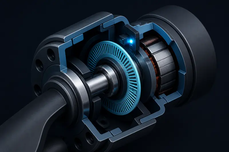
Every robot joint needs to know its own angle, and that means picking an encoder. The absolute vs incremental encoder decision for a robot joint gets covered a lot, but almost always as a qualitative tradeoff table: absolute encoders skip homing, incremental encoders are cheaper. What gets skipped is the actual sizing question: how many bits, or how many pulses per revolution, do you need to hit a specific joint accuracy target? Get this wrong and you either overpay for resolution you can't use, or build a joint that can't hold the position you asked for.
Absolute vs Incremental: The Real Difference
An incremental encoder outputs quadrature pulses (channels A and B, 90 degrees out of phase) as the shaft turns. A microcontroller counts edges to track relative motion. It has no idea what the absolute angle is until it passes a reference, usually an index pulse or a physical homing switch. Lose power mid-motion and the count is gone; the joint has to re-home before it can be trusted.
An absolute encoder outputs a unique code (via SSI, BiSS-C, or an analog/digital protocol) for every distinct shaft position within one turn, or across multiple turns for a multi-turn absolute encoder. Power it up and it reports the real angle immediately, no homing sequence, no lost count if the joint gets bumped while the controller is off.
For a robot arm joint that must be safe to power on in an arbitrary pose (a collaborative arm, a pick-and-place joint near people or fragile parts), absolute encoding is usually worth the extra cost. For a joint that always starts from a known, safe home position, such as most hobby and small mobile-robot builds, incremental is cheaper and simpler. This is the same wiring pattern used in quadrature encoder wiring for a 6-DOF robot arm, which assumes you already picked incremental and need to get channel A/B onto your microcontroller correctly.
Sizing Encoder Resolution for a Target Joint Accuracy
Whichever type you pick, the resolution question is the same: how fine does the encoder need to be so the joint can actually hold the position accuracy your application needs? Work backward from the requirement.
Step 1: Define the required joint accuracy
Say a 6-DOF arm needs its wrist joint to be positioned within 0.05 degrees (3 arcminutes) at the joint itself, a reasonable target for a small precision arm doing light assembly work.
Step 2: Convert to required encoder counts per revolution
One full revolution is 360 degrees. To resolve 0.05 degrees, you need at least:
counts_needed = 360 / 0.05 = 7200 counts per revolutionFor an incremental quadrature encoder, remember that each physical line produces 4 counts (one per edge on both A and B channels), so the required line count (PPR) is:
PPR_needed = counts_needed / 4 = 7200 / 4 = 1800 linesFor an absolute encoder, resolution is usually specified directly in bits. The number of unique positions per revolution is 2^bits, so:
bits_needed = log2(counts_needed) = log2(7200) = 12.8 -> round up to 13 bitsA 13-bit absolute encoder gives 8192 counts per revolution, or 360/8192 = 0.044 degrees per count, comfortably inside the 0.05 degree target. A common off-the-shelf 12-bit encoder (4096 counts, 0.088 degrees per count) would not meet this spec on its own.
Step 3: Account for the gearbox
Most robot joints mount the encoder on the motor shaft, before a gear reduction, not on the output link directly. This works in your favor: the gearbox multiplies the effective output resolution by the reduction ratio. If this joint uses a 50:1 gearbox and a 12-bit (4096 count) absolute encoder on the motor shaft, the effective resolution at the output is:
output_resolution = 360 / (4096 * 50) = 0.00176 degrees per countThat is far finer than the 0.05 degree target, so in this configuration a 12-bit motor-side encoder is actually overkill, and a cheaper 10-bit (1024 count) part would still deliver 360/(1024*50) = 0.007 degrees, well within spec. This is why motor-side encoding is so common: the gear ratio does a lot of the resolution work for free. The tradeoff is that motor-side encoding can't detect backlash or shaft windup between the gearbox output and the encoder; see gearbox backlash compensation for robot arm joints if that matters for your application.
Quantization Error and Control Loop Implications
Resolution sets a hard floor on position error even with a perfect control loop: the joint can never be commanded more precisely than one encoder count, so worst-case quantization error is half a count (+/- 0.5 LSB). For the 1800-line incremental example above, that is +/- 0.025 degrees, half of the original 0.05 degree budget, which is a reasonable margin. If you size resolution exactly to the accuracy target with no margin, sensor noise, gear backlash, and structural compliance will eat into that budget and the joint will underperform its spec on paper. A practical rule of thumb: size for at least 2-4x finer resolution than your final accuracy target, not 1x.
Velocity estimation adds a second constraint. A PID or LQR velocity term differentiates position over a fixed control period. At low encoder resolution and low speed, the joint may barely tick over one count per control cycle, making velocity estimates noisy and quantized in steps rather than smooth. If your joint needs to run slowly and smoothly (a common requirement near the end of a trajectory), that pushes you toward finer resolution than the static position-accuracy calculation alone would suggest. We work through that exact arithmetic, and the estimators that tame it, in our guide to robot joint velocity estimation from encoder counts.
Putting It Together
- Start from the required joint accuracy in degrees or arcminutes, not from a part number.
- Convert to required counts per revolution, then to PPR (incremental) or bits (absolute), applying a 2-4x safety margin.
- If the encoder sits on the motor shaft ahead of a gearbox, multiply resolution by the gear ratio before comparing against your target, this usually lets you use a coarser, cheaper encoder than the naive calculation suggests.
- Choose absolute over incremental when the joint must report a trustworthy position immediately on power-up, without a homing move.
Skipping this sizing step is how builders end up with either an oversized, expensive 20-bit absolute encoder on a joint that only needed 12 bits, or a joint that visibly steps and hunts around its setpoint because the encoder resolution was never checked against the actual accuracy requirement in the first place.
Building or studying robotics?
Arcbotix publishes practical guides on robotics engineering, control systems and real-world builds. Explore more articles on the blog.