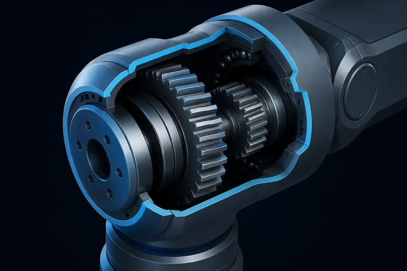
If your robot arm loses a fraction of a degree every time a joint changes direction, the motor and its encoder are probably not lying to you. The gearbox is. Gearbox backlash is the small rotational gap between meshing teeth that lets a gear train reverse a short distance before it actually starts driving the output again. It shows up as a position error that appears only at direction reversals, and it is one of the most common reasons a well-tuned joint still overshoots or fails to return to the same spot from two different directions.
This article covers how to measure backlash from encoder data you already have, and two practical ways to compensate for it in software: dead-band inversion and a lookup table. It assumes a joint with a motor-side encoder and a gearbox between the motor and the output, the same setup covered in our quadrature encoder wiring guide.
What backlash actually looks like in the data
Picture a joint driving clockwise. The motor-side encoder counts up smoothly, and the output moves with it. Now reverse direction. For the first few tenths of a degree of motor rotation, the encoder counts down normally, but the output does not move at all, because the drive-side tooth has to travel across the gap before it contacts the opposite face of the driven tooth. Only after that gap closes does the output start tracking the motor again.
If you only have a motor-side encoder (no separate output-side sensor), you cannot see this gap directly. What you see instead is a repeatable position error at the output whenever direction reverses, typically reported in an end effector position that is consistently off by the same amount depending on which way the joint last moved. This is the classic signature of backlash: an error that depends on direction history, not on absolute position.
Measuring it with a dial indicator and the motor encoder
The most direct way to measure backlash on a bench is:
- Lock the output shaft against a fixed reference, or mount a dial indicator (or a second encoder) on the output.
- Drive the motor slowly in one direction until the output just starts moving. Zero the motor encoder count at that point.
- Reverse the motor direction slowly and count motor encoder ticks until the output starts moving again in the new direction.
- Convert that tick count to degrees using your counts-per-revolution and gear ratio, as covered in the encoder wiring guide.
For a motor encoder with 2000 counts per revolution (500 CPR quadrature-decoded to x4) behind a 50:1 gearbox, if you count 18 motor ticks between direction reversal and output motion, the backlash at the motor shaft is:
backlash_motor_deg = (18 / 2000) * 360 = 3.24 deg
backlash_output_deg = backlash_motor_deg / 50 = 0.0648 deg
0.065 degrees at the output sounds small, but stacked across a 6-DOF arm with cumulative link lengths, that can translate into several millimeters of end-effector error at direction reversal. This is why our harmonic drive vs planetary gearbox comparison treats backlash as a first-order selection criterion: a harmonic drive's sub-1-arcminute backlash (about 0.017 degrees) is almost 4x tighter than a typical planetary stage in this example, before any software compensation.
Measuring it in software from position error alone
If you cannot instrument the output directly, you can estimate backlash from closed-loop behavior. Command a small step in one direction, let the joint settle, then command a small step back toward the original position. The difference between the commanded return position and the actual settled position, measured only in the segment right after a direction change, is your backlash estimate. Average this over several reversals to filter out friction and settling noise. This is noisier than the dial-indicator method but works on a fully assembled robot without disassembly.
Software compensation: dead-band inversion
The simplest compensation method adds a fixed offset to the motor command whenever the direction of travel reverses. The idea: when the controller decides to reverse direction, immediately drive the motor an extra backlash_motor_deg worth of rotation before resuming normal position control, so the gearbox gap closes before the output is expected to respond.
class BacklashCompensator:
    def __init__(self, backlash_deg, motor_cpr, gear_ratio):
        self.backlash_deg = backlash_deg
        self.ticks_per_deg = (motor_cpr * 4) / 360.0  # x4 quadrature decoding
        self.gear_ratio = gear_ratio
        self.last_direction = 0

    def compensate(self, target_motor_ticks, current_direction):
        if current_direction != 0 and current_direction != self.last_direction:
            offset_ticks = self.backlash_deg * self.ticks_per_deg * current_direction
            target_motor_ticks += offset_ticks
        if current_direction != 0:
            self.last_direction = current_direction
        return target_motor_ticks
This runs upstream of your position controller (PID or LQR, see our LQR control introduction for an alternative to PID here): the compensator adjusts the setpoint fed to the controller, not the controller gains themselves. The key limitation is that dead-band inversion assumes backlash is constant across the joint's full range of motion, which is true for a fresh, well-manufactured gearbox but becomes less true as gear teeth wear unevenly.
Software compensation: lookup table
Backlash is rarely perfectly uniform, especially in gearboxes that see uneven load distribution across their range (a shoulder joint holding weight at different arm extensions, for example). A lookup table stores measured backlash at several positions across the joint's range and interpolates between them.
import numpy as np

class BacklashLookupTable:
    def __init__(self, position_points_deg, backlash_points_deg):
        # position_points_deg: measured joint angles, ascending
        # backlash_points_deg: backlash measured at each of those angles
        self.positions = np.array(position_points_deg)
        self.backlash = np.array(backlash_points_deg)

    def lookup(self, current_position_deg):
        return float(np.interp(current_position_deg, self.positions, self.backlash))
Building this table means repeating the dial-indicator or step-response measurement at 5-10 positions spread across the joint's travel, then feeding the interpolated value into the same dead-band inversion logic instead of a single fixed constant. This costs more setup time but tracks real gearboxes far more accurately than a single number, and it is worth doing for any joint carrying significant off-axis load, like a shoulder or hip joint in a legged robot.
What compensation cannot fix
Software compensation corrects for a known, repeatable gap. It does not help with:
- Backlash that changes with temperature or load. Thermal expansion and load-dependent elastic deflection shift the effective gap, and a static lookup table will drift out of calibration over time or across operating conditions.
- Wear-induced backlash growth. As gear teeth wear, backlash increases, usually unevenly across the range of motion. A table calibrated when the gearbox was new degrades gradually and needs periodic recalibration.
- High-precision applications with tight cycle times. The dead-band inversion move takes real time to execute; on a fast, high-duty-cycle joint this adds a small but nonzero settling delay every time direction reverses.
For joints where any of these matter, the more robust fix is mechanical: preloaded anti-backlash gear pairs, a lower-backlash gearbox architecture like a harmonic drive, or adding an output-side encoder so the controller closes the loop after the gearbox instead of before it. Output-side sensing eliminates the backlash error from the control loop entirely, at the cost of an extra sensor and, in some architectures, reduced loop stability margin because the gearbox compliance now sits inside the feedback path.
Choosing between compensation and elimination
Software compensation is the right first step for most hobbyist and mid-precision builds: it is free, requires no extra hardware, and typically cuts backlash-driven position error by 70-90% for a well-characterized joint. Reach for mechanical elimination (better gearbox, anti-backlash preload, or dual encoders) only when compensation still leaves more error than your application tolerates, or when the joint's load profile makes backlash too variable for a static table to track. Measure first, either way. A joint that turns out to have 0.02 degrees of backlash at the output is not worth the engineering time a joint with 0.5 degrees demands.
Building or studying robotics?
Arcbotix publishes practical guides on robotics engineering, control systems and real-world builds. Explore more articles on the blog.