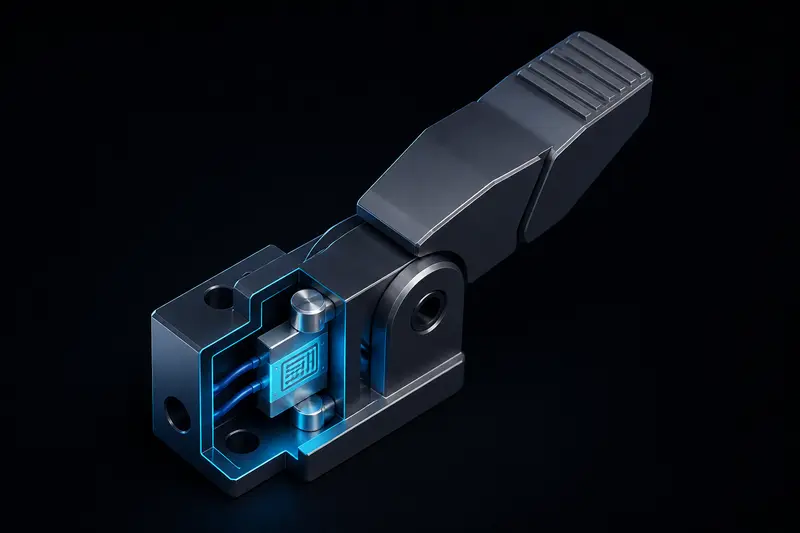
Most small grippers control force indirectly, by watching motor current and hoping it correlates with grip pressure. That works until friction, gear preload, or a worn cable changes the relationship. A load cell gives you a direct, calibrated force measurement at the point of contact, which is what you actually want to control. This article walks through robot gripper force control from a raw strain gauge signal to a tuned PID force loop, using one concrete numeric example end to end.
Why load cell force sensing beats current sensing for a gripper
Current sensing estimates torque at the motor shaft, then infers force at the fingertip through the gear ratio and linkage geometry. Any backlash, friction, or belt stretch between the motor and the contact point turns into force estimation error. A load cell sitting directly in the finger's load path removes that chain of assumptions: it measures the force where the part actually touches the object.
The tradeoff is signal quality. A load cell's raw output is a few millivolts across a resistive bridge, buried in noise, and it needs real calibration before the number means anything in grams or newtons. That calibration work is the part most gripper writeups skip.
The strain gauge bridge
A typical miniature load cell (for example a 5 kg or 10 kg beam-type cell) is a Wheatstone bridge of four strain gauges bonded to a metal beam. Under load, the beam flexes a fraction of a millimeter, two gauges stretch and two compress, and the bridge produces a differential voltage proportional to strain. The key spec on the datasheet is rated output, typically given in mV/V: for example, 2.0 mV/V at rated capacity.
For a 5 kg (49 N) load cell excited at 5 V with a 2.0 mV/V rating:
Full-scale bridge output = 5 V × 2.0 mV/V = 10 mV at 49 N
That means 1 N of force produces roughly 0.204 mV of bridge output. This is far too small and too noisy to feed straight into a microcontroller's ADC.
Amplifying and digitizing the signal
An instrumentation amplifier (such as an HX711 module, common on hobby load cells, or a discrete INA125-style chip) sits between the bridge and the ADC. The HX711 has a fixed internal gain of 128 on channel A, and outputs a 24-bit digital value directly, so there is no separate external ADC step. Using the numbers above:
Amplified output = 0.204 mV/N × 128 = 26.1 mV/N (referred to the amplifier's internal full-scale range)
With a 24-bit ADC and a differential input range of roughly ±20 mV (typical for the HX711 at gain 128, referenced to a 5 V excitation), the code-to-force scale factor becomes a single calibration constant you compute once and store:
scale_factor (counts per newton) = (raw_reading_at_known_load - raw_reading_at_zero_load) / known_load_in_newtons
In practice you find this constant experimentally, not purely from datasheet math, because amplifier gain tolerance and cable resistance shift the real number. The procedure:
- Read the raw ADC value with nothing on the load cell. Call this
raw_zero. This is your tare offset. - Hang a known calibration mass (a 500 g weight is a convenient bench reference) and read the raw value. Call this
raw_cal. - Compute
scale_factor = (raw_cal - raw_zero) / (0.500 kg * 9.81 m/s^2), giving counts per newton. - For any later reading:
force_N = (raw_reading - raw_zero) / scale_factor.
Worked example with plausible numbers: raw_zero = 8,388,000, raw_cal = 8,507,500 after hanging 500 g (4.905 N):
scale_factor = (8,507,500 - 8,388,000) / 4.905 N = 119,500 / 4.905 = 24,363 counts/N
Now if the gripper is squeezing an object and the live reading is 8,461,000:
force_N = (8,461,000 - 8,388,000) / 24,363 = 73,000 / 24,363 = 3.0 N
That is the number your control loop actually uses. Repeat the two-point calibration with a second known mass to confirm linearity; strain gauge load cells are linear to within about 0.1-0.5% of full scale over most of their range, so a two-point fit is normally sufficient for gripper work.
Closing a PID loop on measured force
Once you have a clean, calibrated force reading at some update rate (the HX711 typically outputs 10 or 80 samples per second, low enough that you should low-pass filter or average a few samples before feeding the controller), the force loop looks structurally identical to a position loop, except the setpoint and feedback are both in newtons instead of radians.
error = force_setpoint - force_measured
integral += error * dt
derivative = (error - previous_error) / dt
motor_command = Kp * error + Ki * integral + Kd * derivative
previous_error = error
A concrete starting point for a small gripper finger driven by a geared DC motor: target grip force 3.0 N on a plastic part, sample time dt = 0.02 s (50 Hz, well within the HX711's practical rate after averaging).
Start conservative and raise gain until you see the first sign of oscillation, then back off:
Kp = 40(motor duty-cycle percent per newton of error) as a first guess, since even a large 3 N error should not saturate the driver.Ki = 15, small enough that integral windup does not overshoot once contact is made; this term mainly corrects the small steady-state offset from static friction in the finger linkage.Kd = 2, just enough to damp the sudden step in force when the finger first touches the object, which is the main source of overshoot in force control (contact events are much sharper transients than typical position moves).
Clamp the integral term and the final motor command to the driver's safe duty-cycle range, and clamp motor_command to zero or negative (open the finger slightly) if force_measured exceeds a hard safety ceiling, for example 1.5 times the setpoint, so a control glitch cannot crush a fragile part. This is the same current-limiting instinct used in torque control for robot arm joints from motor current sensing, just applied to a direct force measurement instead of an inferred one.
Contact detection: the step you cannot skip
A force PID loop should not run continuously while the finger is moving through open air, because the error term (setpoint minus zero) would drive the motor at full command before any contact exists. The usual structure is a two-phase state machine:
- Approach phase: position or velocity control closes the gripper at a moderate speed while the force reading is monitored but not used as the control variable.
- Contact phase: the instant
force_measuredcrosses a small threshold (for example 0.2 N, well above sensor noise floor but well below the target), switch control mode to the force PID loop described above, with the setpoint held at the target grip force.
This threshold-triggered handoff, not the PID gains themselves, is usually what determines whether a gripper feels smooth or slams into objects.
Practical calibration checklist
- Always re-tare (re-read
raw_zero) right before each grip cycle if the gripper orientation changes, since gravity loading on the load cell itself shifts the zero point. - Excitation voltage drift changes the mV/V output directly; if you are not using a ratiometric ADC like the HX711 (which measures relative to its own excitation), regulate the excitation supply.
- Temperature affects gauge resistance; for hobby-grade grippers operating indoors at roughly constant temperature this is usually negligible, but it matters for outdoor or thermally cycled applications.
- Mechanical creep in the load cell's beam after sudden loading can shift readings by a small percentage over a few seconds; if your grip cycles are fast this rarely matters, but for sustained holds, expect a small reading drift.
The full chain, from a 2.0 mV/V bridge rating through a known 128x gain and a two-point calibration to a scale factor in counts per newton, then into a PID loop with a contact-detection threshold, gives you a gripper that actually controls force at the fingertip instead of guessing from motor current.
Building or studying robotics?
Arcbotix publishes practical guides on robotics engineering, control systems and real-world builds. Explore more articles on the blog.