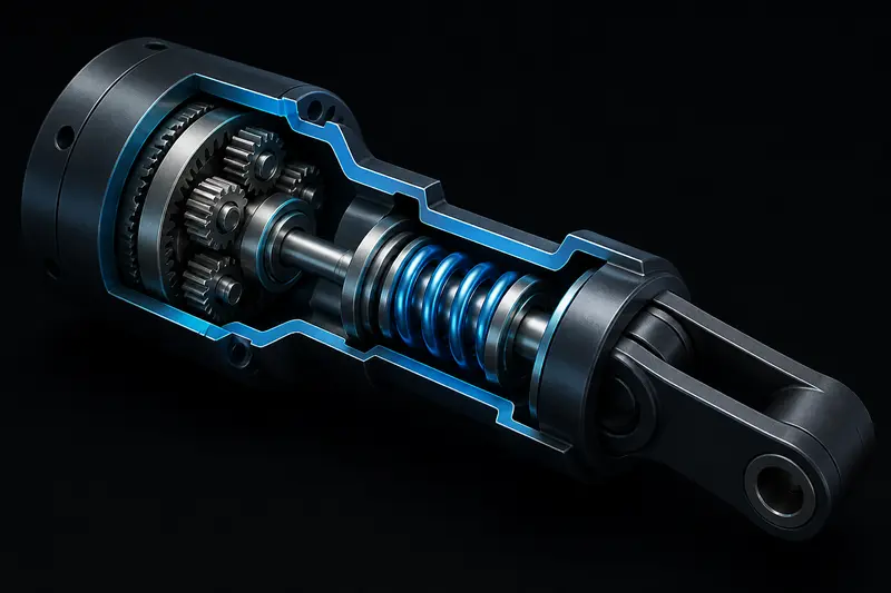
A series elastic actuator (SEA) puts a compliant element, usually a torsional spring, between the gearbox output and the joint's link. This is the opposite of how most robot arm joints are built: normally you want the drivetrain as stiff as possible so that a commanded position translates directly into a real position. An SEA design deliberately gives that up. In return you get low output impedance, tolerance to impact loads, and a straightforward way to measure joint torque - you read the spring's deflection instead of adding a separate torque sensor.
The problem with most series elastic actuator design writeups is that they stop at the concept. They explain why compliance helps force control and human-robot interaction, then move straight to a research paper's finished prototype. Nobody shows you how to pick the actual number: what torsional stiffness, in Nm/rad, should the spring have for your joint. This article walks through that calculation for a concrete example.
Why series elastic actuator stiffness is a real design variable
The spring in an SEA is not just a shock absorber. Its stiffness k (Nm/rad) sets a tradeoff between two things you care about directly:
- Torque resolution and safety margin. A softer spring deflects more for a given torque, so a fixed-resolution position sensor across the spring gives you finer torque resolution. It also means the mechanism physically yields before something breaks during an unexpected impact.
- Force control bandwidth. A softer spring also lowers the natural frequency of the coupled system (motor-side inertia against the spring), which caps how fast your torque control loop can respond. Too soft, and the joint feels sluggish and can even become underdamped and oscillate under closed-loop force control.
This is a real design tradeoff, not a rule of thumb. Get it wrong in the stiff direction and you have lost most of the benefit of adding a spring at all. Get it wrong in the soft direction and your force control loop cannot hit the bandwidth you need.
The governing relationship
Model the SEA as a two-inertia system: motor and gearbox inertia J_m on one side of the spring, load inertia J_l on the other, coupled by spring stiffness k. The resonance frequency that limits your achievable closed-loop torque bandwidth is approximately:
omega_n = sqrt(k * (1/J_m + 1/J_l))
As a practical design rule, most SEA implementations aim for this resonance to sit at least 3-5 times above the desired closed-loop torque control bandwidth, so the control loop has margin before it runs into the spring's structural dynamics.
Worked example: sizing a spring for a 30 Nm arm joint
Take a mid-size robot arm shoulder joint with these targets:
- Peak joint torque:
T_peak = 30 Nm - Desired closed-loop force control bandwidth:
f_bw = 8 Hz(a reasonable target for compliant manipulation, not high-speed dynamic legged locomotion) - Reflected motor-side inertia (motor + gearbox, referred to the joint):
J_m = 0.004 kg*m^2 - Link-side inertia at this joint:
J_l = 0.03 kg*m^2 - Maximum allowed spring deflection at peak torque:
theta_max = 12 degrees = 0.209 rad(a mechanical stop limit you set for packaging reasons)
Step 1: minimum stiffness from deflection limit
The spring must not bottom out before reaching peak torque. That gives a lower bound on stiffness:
k_min = T_peak / theta_max = 30 / 0.209 = 143.5 Nm/rad
Step 2: check the resonance against your bandwidth target
Target resonance, with a 4x margin over the 8 Hz bandwidth:
omega_n_target = 2*pi*(4*8) = 201 rad/s
Solve the two-inertia formula for k:
k = omega_n_target^2 / (1/J_m + 1/J_l)
1/J_m + 1/J_l = 1/0.004 + 1/0.03 = 250 + 33.3 = 283.3
k = 201^2 / 283.3 = 40401 / 283.3 = 142.6 Nm/rad
The two numbers land almost on top of each other here (143.5 vs 142.6 Nm/rad), which is a useful sanity check: at this joint size, the deflection-limit constraint and the bandwidth constraint agree. If they disagreed by an order of magnitude, that would tell you either the deflection limit is too tight for the bandwidth you want, or the bandwidth target is unrealistic for the inertia you have. In that case the fix is usually to loosen the mechanical deflection stop, increase gearbox reduction to raise reflected motor inertia, or accept a lower bandwidth target. Pick k = 145 Nm/rad and specify that stiffness to your spring or flexure manufacturer.
From spring deflection to measured torque
Once the spring is built, you calibrate it rather than trust the nominal stiffness, because real torsion springs and flexures vary a few percent from their design value and often have a small nonlinearity near zero deflection.
- Lock the load side of the joint rigidly.
- Apply a series of known reference torques (a calibrated weight on a known lever arm works well) from zero up to
T_peak. - At each step, record the deflection angle measured by your sensor (an encoder or potentiometer reading the relative angle across the spring).
- Fit torque versus deflection. Use a straight line if the data looks linear; use a quadratic or piecewise fit if you see softening or stiffening near the ends of travel.
For this example, a clean linear fit gave a measured stiffness of k_measured = 138 Nm/rad, about 5% below the 145 Nm/rad design target. That is well within normal spring manufacturing tolerance. Use k_measured, not the datasheet or design value, in your torque control firmware:
T_measured = k_measured * (theta_output_side - theta_motor_side)
Any deflection sensor offset must also be zeroed with the joint unloaded before this calibration is valid, the same way you would zero an encoder-based joint before using it, as covered in our homing and encoder-offset article.
Common mistakes when sizing SEA stiffness
- Choosing stiffness from a paper built for a different scale. A humanoid ankle SEA and a small arm shoulder SEA can differ in required stiffness by two orders of magnitude. Always run the inertia and bandwidth numbers for your own joint.
- Ignoring the motor-side inertia term. It is tempting to size stiffness only from the load inertia. At low gear ratios, motor-side inertia dominates the two-inertia resonance and changes the answer significantly.
- Skipping calibration. Using the nominal spring rate instead of a measured one introduces a torque error that is constant in percentage terms but grows in absolute Nm at high load, exactly where accurate force control matters most.
Conclusion
Series elastic actuator design is not just a spring bolted in series with a motor. The stiffness value is a first-order design decision that trades deflection range and torque resolution against force control bandwidth, and it follows directly from the two-inertia resonance formula once you know your joint's peak torque, target bandwidth, and reflected inertias. Compute a candidate stiffness from both the deflection limit and the bandwidth target, check that they roughly agree, and then calibrate the built spring's actual torque-deflection curve rather than trusting the design number in your control loop.
Building or studying robotics?
Arcbotix publishes practical guides on robotics engineering, control systems and real-world builds. Explore more articles on the blog.