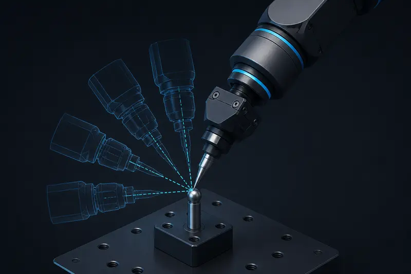
Every motion command a robot controller executes internally targets the flange, the mounting plate at the end of the last joint. But you almost never care where the flange is. You care where the tool tip is: the welding electrode, the gripper fingertip, the router bit. TCP calibration is the step that tells the controller the fixed offset between those two points, so that every jog, waypoint, and path you teach actually happens where the tool touches the work, not where the flange happens to be.
Get this offset wrong and the symptom is distinctive: command a pure reorientation move, rotating the wrist in place with no translation, and instead of staying still the tool tip swings through a small cone or arc. That happens because the controller is rotating the flange correctly, but it is rotating around the wrong point, since it does not know where the real tip is relative to the flange.
What TCP Calibration Actually Solves For
Let p_flange be the flange position in the robot's base frame and R_flange be the 3x3 rotation matrix describing the flange orientation, both of which the controller always knows from forward kinematics. The tool tip position in the base frame is:
p_tip = p_flange + R_flange * t
where t is the unknown offset vector, expressed in the flange's own coordinate frame, from the flange origin to the tool tip. TCP calibration is nothing more than solving for t. Once you have it, the controller can add R_flange * t to every planned flange pose and command paths in tool-tip coordinates instead of flange coordinates.
The Pivot Calibration Procedure
The standard approach, sometimes called the four-point or pivot method, is simple to describe: pick any fixed point in space, a pin tip, a scribed mark, the corner of a jig, and jog the robot so the tool tip touches that exact point. Record the flange pose. Then rotate the wrist to a substantially different orientation, jog again until the tip touches the same fixed point, and record that pose too. Repeat for three or four total poses, spanning as much orientation diversity as the wrist allows.
Every vendor's documentation stops there and says the software calculates the offset. It does, but the calculation is a small least-squares problem you can set up yourself, which is useful both for understanding why four poses beat two and for sanity-checking a calibration that looks suspicious.
Setting Up the Least-Squares System
Since the tool tip touches the same physical point p_fixed in every pose, each recorded pose i gives:
p_flange_i + R_i * t = p_fixed
Both t and p_fixed are unknown, six unknowns total in 3D. Rearranged into standard linear form:
R_i * t - p_fixed = -p_flange_i
Stack this for N poses into a big matrix equation A x = b, where x = [t; p_fixed], and solve with the normal equations x = (A^T A)^-1 A^T b. Two poses give six equations for six unknowns, technically solvable, but in practice unreliable because measurement noise has nowhere to average out. Three or four poses with the wrist rotated through clearly different, non-parallel axes is the practical minimum for a repeatable calibration.
A Worked Numeric Example
To keep the arithmetic checkable by hand, work the planar case: a wrist that only rotates about one axis, with the tool offset and fixed point both in that plane. The 3D case is the same idea with a full rotation matrix instead of a 2D one.
Suppose the true (unknown to us, known to the simulation) tool offset is tx = 50 mm, ty = 0 mm in the flange frame, and the fixed pin is at p_fixed = (400, 150) mm. Teaching four poses 90 degrees apart gives these recorded flange positions:
- theta = 0 deg: flange at (350.0, 150.0) mm
- theta = 90 deg: flange at (400.0, 100.0) mm
- theta = 180 deg: flange at (450.4, 149.6) mm (0.4 mm off due to teach-pendant jog resolution)
- theta = 270 deg: flange at (400.0, 200.0) mm
Poses 180 degrees apart give a shortcut worth knowing: since R(theta+180) * t = -R(theta) * t, the offset term cancels when you average opposite poses, leaving p_fixed directly.
- Average pose 1 and pose 3: ((350.0+450.4)/2, (150.0+149.6)/2) = (400.2, 149.8) mm
- Average pose 2 and pose 4: ((400.0+400.0)/2, (100.0+200.0)/2) = (400.0, 150.0) mm
- Average both estimates: p_fixed = (400.1, 149.9) mm
The true fixed point was (400, 150) mm, so this estimate is off by about 0.14 mm, entirely attributable to the 0.4 mm jog error in pose 3. Now solve for t using pose 1: t = p_fixed - p_flange_1 = (400.1 - 350.0, 149.9 - 150.0) = (50.1, -0.1) mm, close to the true (50, 0) mm. A full least-squares solve using all four poses together, rather than just averaging opposite pairs, would spread that 0.4 mm error across all four residuals instead of concentrating it in one pair, which is the real reason four-plus poses outperform the minimum.
Reading the Residual
After solving, plug your estimated t and p_fixed back into the original equations for every pose and check the residual, the leftover error at each pose. A residual under roughly 0.2 to 0.5 mm across all poses is typical for a rigid tool mount and a careful jog. If one pose has a residual several times larger than the others, that pose was probably mistaught, or the tool is not actually rigid, a loose collet or a bent probe will produce exactly this kind of outlier.
If the residual is small for three poses but large for a fourth, re-teach that one pose before trusting the calibration. Averaging a bad pose into a least-squares fit hides the error instead of fixing it.
This TCP offset feeds directly into whatever inverse kinematics solver plans your paths, since path waypoints are specified at the tool tip and must be converted back to a flange target before the solver runs. It is a similar layered-calibration idea to homing a joint's encoder offset: one calibration establishes where zero is at the joint level, this one establishes where the working point is at the tool level, and both have to be right before any taught path means what you think it means.
Practical Notes
- Use as much orientation spread as the wrist allows. Poses that only differ by a small rotation angle make the rotation matrices nearly identical, which makes the least-squares system poorly conditioned and amplifies noise into the solution.
- Re-run the calibration whenever the tool is removed and reinstalled, even onto the same mount. A collet or quick-change coupler rarely returns to the exact same seated position twice.
- For tools with a meaningful orientation component (a spray nozzle, a laser), pivot calibration alone only gives you the translational offset. A second step, aligning a reference axis of the tool to a known direction, is needed to fix the rotational part of the tool frame.
Building or studying robotics?
Arcbotix publishes practical guides on robotics engineering, control systems and real-world builds. Explore more articles on the blog.