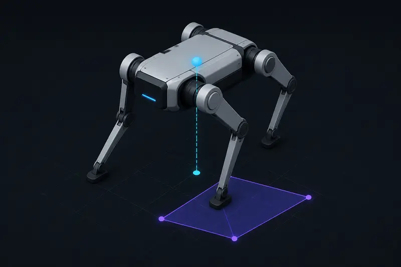
The zero moment point (ZMP) is the standard stability criterion for legged robots: a point on the ground where the net moment of all forces acting on the robot, projected onto the ground plane, is zero. If that point stays inside the robot's support polygon, the robot is dynamically balanced. If it leaves the polygon, the robot tips. Most explanations of the zero moment point for legged robot balance stop at the definition. This article works through the actual numbers for a simple stance so you can compute it for your own robot.
What the Zero Moment Point Actually Measures
A static robot only needs its center of mass (CoM) above its support polygon to stay upright. A moving robot is different: acceleration of the CoM creates inertial forces that shift the effective point where ground reaction forces must act to keep the robot from rotating. The zero moment point accounts for this. It is not the CoM projection, it is the point where the horizontal moment caused by gravity, inertia, and any external forces cancels out.
For a robot with a roughly constant CoM height (a reasonable approximation during a stance phase or slow gait), the ZMP position along one horizontal axis is:
x_zmp = x_com - (z_com / g) * x_com_ddot
where x_com is the horizontal CoM position, z_com is the CoM height above the ground, g is gravitational acceleration (9.81 m/s^2), and x_com_ddot is the horizontal CoM acceleration. The same formula applies independently along the y-axis. This is the simplified cart-table or linear inverted pendulum form, and it is accurate enough for most hobbyist and mid-size legged robots as long as the CoM height stays roughly constant and foot contact stays flat.
Worked Example: A Quadruped in Single-Support Stance
Take a small quadruped robot with the following numbers during a trot gait, at the instant one diagonal pair of legs is in the air and the robot is supported by a single front-left and rear-right foot pair (a two-point support 'line' rather than a full polygon, which is the harder case to balance):
- CoM height: z_com = 0.18 m
- CoM horizontal position (from the midpoint of the support line): x_com = 0.02 m
- CoM horizontal acceleration: x_com_ddot = 0.6 m/s^2 (the robot is accelerating forward as it pushes off)
Plugging into the formula:
x_zmp = 0.02 - (0.18 / 9.81) * 0.6 = 0.02 - 0.011 = 0.009 m
The ZMP sits 9 mm forward of the support-line midpoint, only slightly ahead of where the CoM itself is. Now compare that to the support polygon. For a diagonal two-foot support pattern, the 'polygon' collapses to a line segment between the two contact points, and a real 2D margin only exists once the next foot lands. If the two support feet are 0.14 m apart along the line and the ZMP's lateral offset from that line is under about 0.01 m (accounting for foot pad width), the robot is still within tolerance. If x_com_ddot had instead been 3.5 m/s^2 from a sudden lunge, the shift term becomes (0.18/9.81) * 3.5 = 0.064 m, an offset large enough to push the ZMP off the support line entirely, meaning the robot would need the next foot down before that acceleration happens, not after.
Checking Against the Support Polygon
With four feet on the ground, the support polygon is the convex hull of the foot contact points, typically a rectangle roughly 0.15 m by 0.25 m for a small quadruped. The stability check is simple in principle:
- Compute x_zmp and y_zmp from the CoM trajectory using the formula above.
- Compute the support polygon vertices from the current foot placements.
- Check whether (x_zmp, y_zmp) lies inside the polygon, with a safety margin (commonly 10-20 mm) subtracted from each edge to account for foot pad compliance and model error.
In code, the point-in-polygon check is a standard geometric test (ray casting or the cross-product sign method), applied every control cycle as the CoM trajectory is planned or replanned. Static-only stability margin from the CoM projection alone would have called the single-support example above safe (since x_com = 0.02 m is closer to the midpoint than x_zmp), while ZMP correctly shows the inertial term pushing the effective stability point further from center, which is the entire reason the criterion exists.
Where ZMP Breaks Down
The linear inverted pendulum simplification assumes constant CoM height and flat, rigid ground contact. It degrades in three common situations:
- Large CoM height changes, such as a jumping or crouching gait, where the vertical acceleration term (usually dropped) becomes significant.
- Soft or uneven terrain, where the actual ground reaction point does not match the assumed rigid contact geometry.
- Fast dynamic gaits (running, hopping) where the robot is airborne for part of the cycle and there is no support polygon at all; stability there is judged by different criteria, such as the capture point.
For a walking or trotting gait on flat ground at moderate speed, though, the ZMP formula above is the right tool, and it is exactly the reference signal that a balance controller regulates to zero relative to the support polygon center. A common way to build that controller is with a state-space regulator: see our LQR control practical introduction for the mechanics of setting up the state-space model and cost weights that a ZMP-tracking balance loop would use.
Practical Notes for Implementation
A few numbers worth keeping in mind when you compute this for your own robot:
- Measure z_com from your actual robot's mass distribution, not just the body height off the ground; leg mass shifts the effective CoM height noticeably on a light robot.
- Estimate x_com_ddot from your planned CoM trajectory (if you are pre-computing a gait) or from IMU/kinematic state estimation in real time; a noisy acceleration estimate will make the ZMP jump around even when the robot is actually stable.
- Build in the safety margin on the polygon edges before you rely on this in hardware. A margin of 15-20% of the polygon's shortest dimension is a reasonable starting point for a small robot with some foot compliance.
The core idea is simple once you have run the numbers once: the zero moment point is just the CoM projection corrected for how hard you are accelerating it, and keeping that corrected point inside your feet is what keeps a legged robot from tipping over.
Building or studying robotics?
Arcbotix publishes practical guides on robotics engineering, control systems and real-world builds. Explore more articles on the blog.