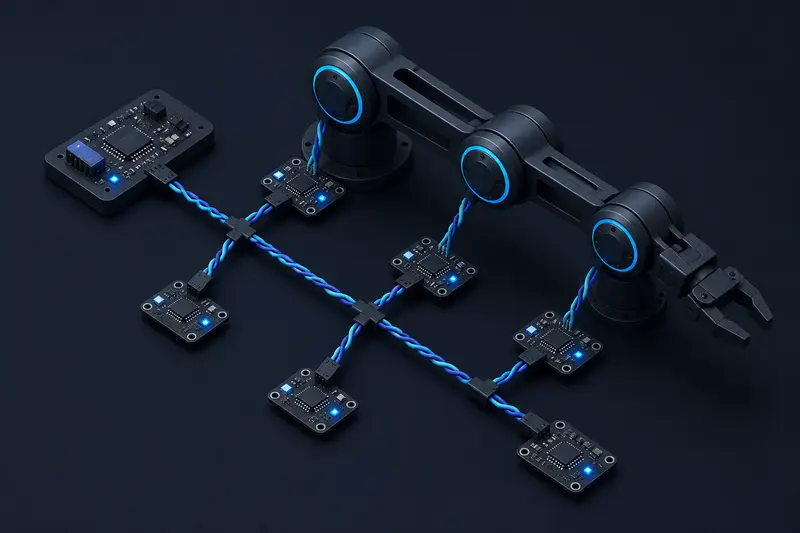
A robot arm with six joints, each running its own motor controller, needs a way for those controllers to talk to each other and to a central computer. CAN bus for robot joint networks is a common choice because it is a two-wire, multi-drop bus that keeps wiring simple and tolerates electrical noise well. The concept gets explained often, but the numbers that actually determine whether your network works, cable length versus bit rate, termination placement, and how much bus capacity your messages actually consume, rarely get worked through. This article does that with a concrete 6-joint arm example.
Why CAN Bus for Robot Joint Networks
Each joint controller (say, a BLDC driver doing current-sensed torque control) needs to receive a target and report status: position, current, temperature, fault flags. Running a dedicated wire pair to each joint for this is a wiring nightmare on a 6-DOF arm. CAN bus solves this by putting every joint controller on the same two-wire differential pair (CAN-H and CAN-L), daisy-chained from joint to joint. Any node can transmit, every other node hears every message, and a hardware arbitration scheme resolves collisions without corrupting data. That's the appeal: six controllers, one pair of wires, no host-mediated polling.
Bus Topology and Termination
CAN is a linear bus, not a star. Each joint controller taps into the same pair as it goes, with the two physical ends of the bus terminated by a 120 ohm resistor. The characteristic impedance of a standard CAN twisted pair is close to 120 ohms, so a 120 ohm resistor at each end absorbs the signal and prevents it from reflecting back down the line. Two termination points total, never one per node. A common mistake on a first joint-network build is adding a 120 ohm resistor at every joint controller instead of just the two end nodes: with six nodes that drops the effective parallel resistance to 20 ohms, which pulls the bus voltage swing down and can push a driver outside its valid differential voltage range, causing intermittent bit errors that look like random communication dropouts rather than an obvious wiring fault.
Bit Timing: Matching Baud Rate to Cable Length
CAN's arbitration relies on every node sampling the bus at the same point in each bit, which means the signal has to physically propagate from the farthest node and back within a fraction of one bit time. This is where cable length limits come from, and they are easy to derive.
Signal propagation on a typical twisted pair runs at roughly 5 ns per meter. For a worst-case round trip (transmitter at one end, receiver at the other, and the receiver's response has to be seen back at the transmitter before the sample point), the propagation delay budget is:
t_prop = 2 x length x 5 ns/m
For a 1 Mbps bus, one bit time is 1000 ns, and standard CAN controllers reserve roughly 30 to 40% of the bit for the propagation segment plus phase buffers, so a practical budget is about 300 to 400 ns for propagation. Plugging that in:
300 ns = 2 x length x 5 ns/m → length = 30 m
This matches the commonly cited 40 m limit for 1 Mbps CAN once transceiver and connector delays are added in. On a 6-joint arm, the physical cable from base to wrist rarely exceeds 2 to 3 meters, so 1 Mbps is well within budget. The number matters more once you add a long umbilical between the arm base and a remote controller box: at 5 meters of arm wiring plus 15 meters of umbilical, you're at 20 meters, still fine at 1 Mbps, but worth checking rather than assuming.
If your application needs a longer run, say a mobile-base-to-arm link of 40 meters, drop to 500 kbps. At 500 kbps the bit time doubles to 2000 ns, so the propagation budget roughly doubles too, comfortably covering 40 meters with margin. This is the actual tradeoff: bus length and bit rate are linked, and picking 1 Mbps for a network with a long cable run is the single most common cause of unexplained frame errors on a first build.
Bus Load: Do Your Messages Actually Fit?
Getting the electrical layer right does not guarantee the bus has enough capacity for your traffic. A standard CAN frame with an 8-byte payload takes about 130 bits including arbitration ID, control fields, CRC, and stuffing bits, so on a 1 Mbps bus one such frame takes roughly 130 microseconds to transmit.
Consider a 6-joint arm where every joint controller sends a status frame (position, current, fault flags) at 1 kHz, the same rate as the torque control loop:
6 joints x 1000 frames/s x 130 us/frame = 780,000 us of bus time per second = 78% bus load
That is already tight, and it does not leave room for command frames going the other way, or for retransmissions after an error frame. In practice this is why joint status is rarely broadcast at full control-loop rate: dropping status reporting to 200 Hz brings the same six joints down to about 16% bus load, leaving plenty of headroom for command frames, occasional configuration messages, and error recovery. The controller can still run its own torque loop internally at 1 kHz using local encoder and current readings; only the values other nodes need to see have to cross the bus, and they rarely need to cross it as often as the control loop runs.
This distinction, separating what a joint controller needs internally at full rate from what it needs to report externally at a much lower rate, is the single biggest lever for keeping a CAN-based joint network from saturating as you scale from a 6-DOF arm to a 12 or 18 axis system.
Arbitration IDs as a Priority Scheme
CAN resolves simultaneous transmission by bitwise arbitration: nodes transmit their identifier bit by bit, and a node sending a dominant bit (logical 0) always wins over one sending a recessive bit (logical 1), non-destructively, without either message being corrupted. This means the numerically lowest arbitration ID always wins the bus, which turns ID assignment into a priority scheme rather than just an address.
- Reserve the lowest IDs (e.g. 0x000 to 0x00F) for an emergency-stop or fault-broadcast message, so it always wins arbitration against routine traffic.
- Assign joint command frames the next block, since a stale command is worse than a stale status read.
- Put periodic status and telemetry frames in the highest ID range, since they can tolerate being delayed a few bit times behind higher-priority traffic.
On a bus already running near 78% load, this ordering is what keeps an e-stop message from getting stuck behind a queue of routine status frames during the exact moment it matters. If two joint controllers are wired for the encoder feedback described in quadrature encoder wiring for a 6-DOF arm, their status frames are a good candidate for that lowest-priority tier, since a missed encoder update for one cycle is recoverable while a missed stop command is not.
Putting It Together
A working CAN joint network for a robot arm comes down to three numbers you can actually calculate before you wire anything: pick a bit rate the cable length supports (1 Mbps for a few meters, drop to 500 kbps or lower past about 40 meters), terminate exactly the two physical ends with 120 ohms each, and check your bus load against your message rate and frame count rather than assuming it will fit. Getting any one of these wrong produces symptoms that look unrelated to the actual cause: wrong termination shows up as intermittent bit errors, an oversubscribed bus shows up as delayed or dropped status updates under load, and both get blamed on the motor controller firmware before anyone checks the bus math.
Building or studying robotics?
Arcbotix publishes practical guides on robotics engineering, control systems and real-world builds. Explore more articles on the blog.