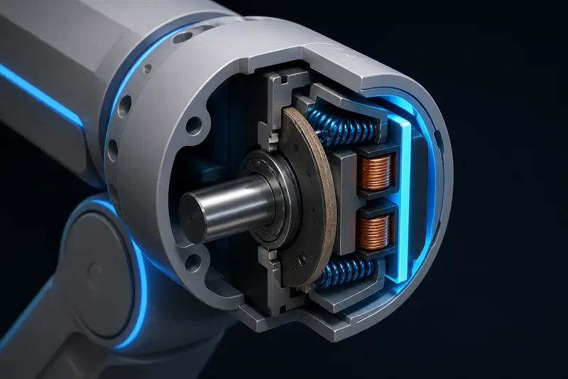
A robot arm joint that fights gravity needs a holding brake, not just a motor that goes limp when the drive disables. If axis 2 or axis 3 of your arm carries a load above the horizontal, cutting power to the motor lets the joint free-fall until something else stops it: a hard stop, the floor, or a person's hand. Holding brake sizing for a robot arm joint means answering one specific question with real numbers: how much static torque does the brake need to hold, and how far does the joint move before the brake actually clamps down.
What a holding brake actually does
A servo holding brake is a small spring-applied, electromagnetically-released disc brake mounted on the back of a motor. Under normal operation the coil is energized, an electromagnet pulls back an armature plate against the spring, and the shaft spins free. Cut the coil voltage (intentionally, or because of an e-stop or power loss) and the spring re-engages the friction disc in tens of milliseconds. This is the opposite failure direction from a normal friction clutch: no power means clamped, not free.
This is not a dynamic brake. It is not rated to dissipate the kinetic energy of a joint decelerating from speed, and running it that way repeatedly will glaze the friction lining and shorten its life fast. Its job is purely static: hold a stationary shaft against a constant load once the joint has already stopped.
Where it fits with other safety hardware
A holding brake is not a substitute for a proper stop circuit. It is a complementary layer: the Category 3 dual-channel e-stop circuit cuts drive enable and removes power fast, and the brake is what keeps a vertical axis from sagging afterward while the arm sits disabled. If your arm only moves in the horizontal plane, or every load-bearing axis is naturally balanced (counterweighted or below a strong enough gearbox worm stage that it cannot back-drive), you may not need one at all. Check backdrivability before assuming a brake is required.
Step 1: Find the gravity torque at the joint
Start at the output shaft, where the physical load actually acts. Take a simple example: axis 2 of a small arm carries a forearm and gripper assembly with a combined mass of 4.0 kg, whose center of mass sits 0.28 m from the joint axis when the arm is extended horizontally, the worst case for gravity torque.
tau_gravity = m * g * l
tau_gravity = 4.0 kg * 9.81 m/s^2 * 0.28 m
tau_gravity = 10.99 N*m
This is the same gravity torque term used in a gravity feedforward calculation for a PD position loop, but here you are not feeding it forward, you are sizing a mechanical part to resist it with zero electronics involved.
Step 2: Decide where the brake sits, output side or motor side
This is the design decision that changes your torque number by orders of magnitude. Most robot arm brakes mount on the back of the motor, before the gearbox, not on the output shaft. That means the required brake torque is the output torque divided by the gear ratio.
Say this joint uses a 50:1 harmonic drive with 85% efficiency. Reflecting the load back to the motor side:
tau_brake,motor = tau_gravity / (N * eta)
tau_brake,motor = 10.99 / (50 * 0.85)
tau_brake,motor = 0.258 N*m
A quarter of a newton-meter is a small, cheap, low-inertia brake instead of an 11 N*m output-side unit. This is why motor-side placement is the default choice on most small and mid-size arms. The tradeoff is that the brake now trusts the gearbox and its coupling to hold too; if a tooth strips or a coupling slips, the brake holds the motor shaft while the joint itself is free. Output-side brakes avoid that failure mode but cost more, add mass at the worst possible location (far from the base), and rarely fit inside a compact joint housing. For most builds, motor-side placement with a gearbox you trust is the right call; only go output-side on safety-critical high-payload axes where gearbox failure has to be tolerated.
Step 3: Apply a safety factor
Never size a brake to its bare calculated torque. Friction linings wear, air gaps grow, coil voltage sags under a shared 24V bus, and your gravity torque estimate itself has some error in the mass and center-of-mass numbers. A safety factor of 2 to 3 on holding torque is standard practice for fail-safe brakes, mirroring the same margin philosophy used when sizing an e-stop's stop-response time budget rather than trusting the nominal spec.
tau_brake,required = 0.258 * 2.5
tau_brake,required = 0.645 N*m
Now you pick the next catalog size at or above 0.645 N*m from a supplier like Mayr, Kendrion, or Miki Pulley. A typical small servo brake line jumps from 0.32 N*m to 0.8 N*m to 2.0 N*m, so you would select the 0.8 N*m unit.
Step 4: Check the free-fall during release time
Sizing the torque only answers whether the brake can hold once engaged. The other question is how far the joint moves before it engages. A spring-applied brake needs 20 to 80 ms to fully re-clamp after the coil de-energizes, and during that window the joint is still being decelerated only by friction and the motor's own detent torque, both small.
Approximate the joint's angular acceleration under gravity torque alone, ignoring friction as a worst case:
alpha = tau_gravity / J_jointFor this arm, if the reflected inertia at the joint (link plus reflected motor/gearbox inertia) is roughly 0.15 kg*m^2, and using an 80 ms worst-case release time:
alpha = 10.99 / 0.15 = 73.3 rad/s^2
delta_theta = 0.5 * alpha * t^2
delta_theta = 0.5 * 73.3 * (0.08)^2
delta_theta = 0.234 rad = 13.4 degrees
Thirteen degrees of drop in the worst case before the brake catches is significant for a joint working near a fixture or a person. If that is not acceptable, the fix is not a bigger brake, it is a faster one: look for a brake spec with a shorter release time, or add mechanical damping (a friction disc, a small dashpot) that limits fall speed independent of the brake.
Practical checklist
- Compute worst-case gravity torque at the output, using the arm pose that maximizes moment arm.
- Decide motor-side vs output-side placement based on how much you trust the gearbox and coupling.
- Reflect torque through gear ratio and efficiency if motor-side.
- Apply a 2 to 3x safety factor before picking a catalog size.
- Check free-fall angle during the brake's rated release time at your worst-case reflected inertia.
- Confirm the brake coil is wired to fail engaged on power loss, not just on a commanded disable.
A brake sized only for static holding torque and never checked against release-time free-fall will pass a bench test and still let a joint drop noticeably in the field, because the bench test rarely reproduces the worst-case pose and reflected inertia together.
Holding brake sizing for a robot arm joint is a short calculation, but skipping the release-time check is the most common mistake: a correctly sized brake can still let a joint swing through a dangerous arc before it actually stops anything.
Building or studying robotics?
Arcbotix publishes practical guides on robotics engineering, control systems and real-world builds. Explore more articles on the blog.