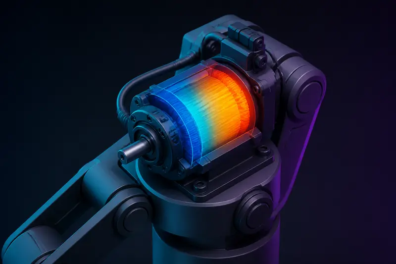
Sizing a motor for a robot joint usually starts with peak torque: can the motor produce enough instantaneous torque to accelerate the link and payload at the worst point in the cycle. That check is necessary but not sufficient. A motor that easily clears the peak-torque requirement can still overheat and fail if it spends too much time near that peak, because winding temperature depends on continuous current, not the instantaneous maximum. This article walks through motor thermal duty cycle sizing for a robot joint with one full worked example: computing the RMS current of a real move-and-hold cycle, comparing it to the motor's continuous current rating, and checking the thermal time constant so you know how long you can safely run above that rating.
Why Peak Torque Alone Is Not Enough
A motor's continuous current rating (Icont) is the current it can sustain indefinitely without exceeding the winding's maximum temperature, given a stated ambient and mounting condition. Its peak current rating (Ipeak) is usually 2 to 5 times higher and can only be sustained for a short window before the copper losses (I²R heating) raise the winding temperature past the insulation's rated limit, typically 130 to 180 degrees C depending on the winding class.
A robot joint motion profile is rarely constant current. It looks like short bursts near Ipeak during acceleration and deceleration, a lower holding current while stationary against gravity or a load, and possibly zero current during a rest phase. The question is whether the time-averaged heating effect of that whole cycle stays under what the continuous rating allows. That average is captured by the RMS (root-mean-square) current of the duty cycle, because heating scales with I², not with I directly.
The RMS Current Formula for a Duty Cycle
For a cycle broken into N segments, each with a roughly constant current Ik lasting duration tk, the RMS current over the full cycle period T is:
IRMS = sqrt( (I1² t1 + I2² t2 + ... + IN² tN) / T )
The sizing rule is simple: if IRMS stays at or below Icont, the motor can run this cycle indefinitely without thermal derating. If IRMS exceeds Icont, you either need a bigger motor, a lower duty cycle (more idle time between cycles), or you need to confirm the excess is short enough relative to the thermal time constant to not matter (covered below).
Worked Example: A Pick-and-Place Joint Cycle
Take a robot arm shoulder joint driven by a motor with Icont = 3.0 A and Ipeak = 9.0 A. The joint performs a repeating 4-second pick-and-place cycle:
- Acceleration phase: 0.4 s at 8.0 A (near-peak current to overcome inertia and gravity torque together)
- Constant-velocity phase: 0.8 s at 2.5 A (mostly overcoming gravity torque and friction)
- Deceleration phase: 0.4 s at 4.5 A (motor braking, partially regenerative but current magnitude still draws through the driver)
- Hold phase (part held at target, arm supporting payload against gravity): 1.4 s at 2.0 A
- Idle phase (arm released, no load torque, only friction): 1.0 s at 0.3 A
Total cycle time T = 0.4 + 0.8 + 0.4 + 1.4 + 1.0 = 4.0 s, which matches.
Now compute the sum of I²t terms:
- 8.0² x 0.4 = 64.0 x 0.4 = 25.6
- 2.5² x 0.8 = 6.25 x 0.8 = 5.0
- 4.5² x 0.4 = 20.25 x 0.4 = 8.1
- 2.0² x 1.4 = 4.0 x 1.4 = 5.6
- 0.3² x 1.0 = 0.09 x 1.0 = 0.09
Sum = 25.6 + 5.0 + 8.1 + 5.6 + 0.09 = 44.39
IRMS = sqrt(44.39 / 4.0) = sqrt(11.10) = 3.33 A
This is above the 3.0 A continuous rating by about 11 percent. On paper, this motor is thermally undersized for continuous operation of this exact cycle, even though its peak current (9.0 A) comfortably clears the highest instantaneous draw in the profile (8.0 A). This is the failure mode that a peak-torque-only check misses: the motor never gets close to its peak rating, but it still runs hot over time because the hold and constant-velocity phases keep contributing heat without enough idle time to dissipate it.
Two Ways to Fix an Overloaded Duty Cycle
First, extend the idle phase. If the idle phase in the example above is stretched from 1.0 s to 2.0 s (T becomes 5.0 s, assuming the added time is at the same 0.3 A idle current, adding 0.09 x 1.0 = 0.09 more to the sum), the new IRMS = sqrt(44.48 / 5.0) = sqrt(8.90) = 2.98 A, which now sits just under the 3.0 A rating. In practice this means slowing down the overall cycle rate (fewer picks per minute) rather than changing anything about the motion itself.
Second, reduce the holding current. The 1.4 s hold phase at 2.0 A contributes the second-largest share of heating after the acceleration burst. If the joint design can support the payload with a mechanical brake or a counterbalance spring during the hold phase instead of active current, that phase's contribution drops close to zero, which has a much bigger effect on IRMS than trimming the short acceleration burst.
Checking Against the Thermal Time Constant
The RMS calculation assumes the winding temperature settles into a steady average, which is valid when the cycle period T is short compared to the motor's thermal time constant (tauth), typically 5 to 30 minutes for small to medium robot joint motors, listed on the datasheet or measurable by running the motor at a known current step and timing the temperature rise to 63 percent of its final value.
If T is much shorter than tauth (as in the 4- or 5-second cycle above, versus a tauth of several minutes), the RMS approximation is safe: the winding thermally averages many cycles together and only "sees" the mean heating rate. If instead your duty cycle period is comparable to or longer than tauth, such as a single long move followed by a long rest, you cannot just average I²t over the whole period. You need to check the peak winding temperature reached during the hot segment directly, using the motor's thermal resistance (Rth, in degrees C per watt) and the exponential heating curve:
Trise(t) = I²Rwinding x Rth x (1 - e-t/tau_th)
For the pick-and-place cycle here, since 4 to 5 seconds is far shorter than any realistic tauth, the RMS check above is the correct and sufficient tool. Save the full exponential check for slow, infrequent, high-duty moves like a single heavy lift held for tens of seconds at a time.
Putting It Into a Sizing Workflow
In practice, thermal duty cycle sizing sits after the peak-torque check described when sizing a motor and gearbox for a robot arm joint, and before finalizing the current control loop described in torque control for robot arm joints. A practical order is:
- Confirm the motor's peak current/torque clears the single worst instant in the motion profile, with margin.
- Break the full repeating cycle into current segments and compute IRMS as shown above.
- Compare IRMS to Icont. If it exceeds it, extend idle time, offload holding torque mechanically, or step up to a larger motor frame.
- If the cycle period approaches the motor's thermal time constant, switch to the exponential temperature-rise check instead of the RMS shortcut.
Skipping straight from "peak torque check passed" to hardware selection is the most common way a joint motor that looks correctly sized on a datasheet still runs hot, trips a thermal cutout, or degrades early in the field. The RMS current check is a five-minute spreadsheet calculation that catches this before the joint is built.
Building or studying robotics?
Arcbotix publishes practical guides on robotics engineering, control systems and real-world builds. Explore more articles on the blog.