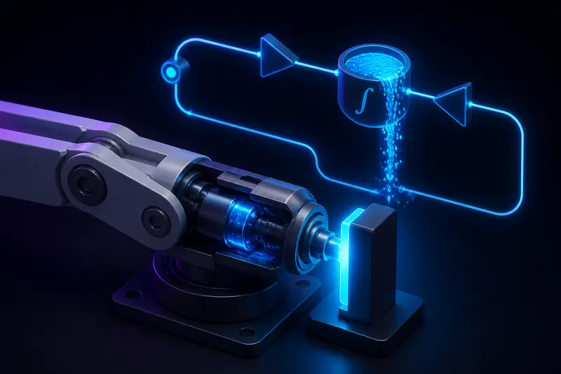
Every real robot joint has a torque limit. The motor driver clamps current, the bus voltage caps speed, and the gearbox has a rated torque you should not exceed. Your PID controller, however, knows nothing about any of that. Command a large step and the controller happily asks for ten times what the actuator can deliver, the output clamps, and the integral term keeps accumulating error the whole time. That stored integral is called windup, and it is why a saturated joint blows past its target and takes ages to settle. This article works through the arithmetic on a concrete joint, then adds the two standard fixes, clamping and back-calculation, as code you can drop into a 1 kHz loop.
What PID Anti-Windup Fixes: The Integrator at the Torque Limit
PID anti-windup addresses one specific failure: the integrator integrating error while the actuator is saturated and physically cannot respond to it. During saturation the feedback loop is effectively broken. The plant gets a constant maximum torque no matter what the controller computes, so the extra integral action does nothing useful now, but it is stored. The moment the error finally shrinks or changes sign, that stored command is still there, pushing the joint past the target until enough negative error has accumulated to drain it back out.
The symptom on a bench is distinctive: the joint launches toward the setpoint at full torque, sails through it, parks noticeably past the target, and then creeps back over several hundred milliseconds. If you have tuned gains using our guide to PID controller tuning for robotic arms and still see this behavior on large steps but not small ones, windup is the first thing to check, because small steps never saturate the actuator.
A Worked Example: A 1.0 rad Step into a 4 N m Torque Limit
Take a single joint with these numbers:
- Reflected inertia about the joint axis: J = 0.05 kg m2
- Actuator torque limit: 4 N m (whichever binds first: driver current limit times torque constant times gear ratio, or the gearbox rating)
- Gains: Kp = 60 N m/rad, Ki = 100 N m/(rad s), Kd = 2 N m s/rad, running at 1 kHz
- Setpoint step: 1.0 rad, about 57 degrees
At t = 0 the proportional term alone asks for 60 x 1.0 = 60 N m, fifteen times the limit. The driver clamps at 4 N m and the joint accelerates at 4 / 0.05 = 80 rad/s2. Starting from rest, position follows q(t) = 40 t2 and the error is e(t) = 1 - 40 t2.
Now watch the integrator. The controller stays saturated until the unsaturated PID output falls back below 4 N m, which for these numbers happens at roughly t = 0.14 s. At that moment:
- The error is still about 0.25 rad, so the joint has not arrived yet.
- The joint is moving at about 11 rad/s.
- The integral of error so far is about 0.10 rad s, so the integral term holds Ki x 0.10 = 10 N m.
Read that last number again: the integrator alone is commanding two and a half times the actuator's entire capability, at a moment when the joint is already flying toward the target at 11 rad/s. To discharge those 10 N m, the integrator needs to accumulate about 0.10 rad s of error on the other side of the target. If the overshoot averages 0.2 rad, that is roughly half a second spent parked on the wrong side while the integral drains. That is the slow, ugly crawl back you see on the bench.
The stored integral is not a tuning problem. No choice of Kp, Ki, Kd fixes it, because the accumulation happens while the loop is broken by saturation. You have to tell the integrator about the limit.
Fix 1: Clamping (Conditional Integration)
The simplest fix is to stop integrating whenever integration would push the output deeper into saturation:
# 1 kHz loop, dt = 0.001, i_state is the integral of error
e = q_ref - q
u_unsat = kp * e + ki * i_state + kd * (0.0 - qdot)  # D on measurement
u = max(-u_max, min(u_max, u_unsat))
saturated = (u != u_unsat)
if not (saturated and e * u > 0):
    i_state += e * dt
tau_cmd = u
The condition reads: if the output is clamped and the error has the same sign as the output, freezing the integrator is the only sane option, because integrating would just demand more of what the actuator cannot give. In the worked example above, clamping keeps the integral near zero during the whole 0.14 s launch, so the controller exits saturation with essentially no stored torque and the overshoot is set by the velocity and the damping term instead of by a 10 N m surprise.
Note the derivative is computed on the measured velocity, not on the error. That avoids the derivative kick on setpoint steps, which would otherwise add its own spike into the saturation.
Fix 2: Back-Calculation and the Tracking Time Constant
Back-calculation is the standard scheme in industrial drives. Instead of freezing the integrator, you feed the difference between the saturated and unsaturated outputs back into it, so the integrator actively unwinds toward a value consistent with the limit:
u_unsat = kp * e + ki * i_state + kd * (0.0 - qdot)
u = max(-u_max, min(u_max, u_unsat))
i_state += (e + (u - u_unsat) / (ki * tt)) * dt
tau_cmd = u
While unsaturated, u equals u_unsat and the extra term vanishes, so behavior is a normal PID. While saturated, (u - u_unsat) is large and negative for a positive step, and it pulls the integral state down with time constant tt.
How do you pick tt? A widely used rule of thumb takes the geometric mean of the integral and derivative times. For our gains, Ti = Kp / Ki = 0.6 s and Td = Kd / Kp = 0.033 s, so tt = sqrt(Ti x Td) is about 0.14 s. Smaller tt unwinds faster but reacts aggressively to brief saturation blips, such as a one-cycle current limit during a load spike. Larger tt drifts back toward plain windup. Anywhere between Td and Ti works; start at the geometric mean and adjust on the bench.
Compared with clamping, back-calculation is smooth, tunable, and degrades gracefully when the saturation is marginal. Clamping is simpler and has no extra parameter. Either one beats doing nothing by a wide margin.
Robot-Specific Details: Gravity Loads and Cascaded Loops
Two things make robot joints different from the textbook process-control setting.
Gravity needs standing torque
A joint holding a horizontal link needs a constant torque just to stay put, and if you provide no feedforward, the integrator is what supplies it. That is legitimate integral action, and neither fix above interferes with it, since both only act during saturation. But a joint whose integrator already carries a large gravity torque sits closer to the limit and winds up faster on top of it. The cleaner architecture is to compute the gravity term explicitly and add it outside the PID, as covered in our worked example on robot arm gravity compensation. With gravity handled by feedforward, the integrator only has to cover friction and model error, and its normal operating value stays small.
Cascaded loops saturate at every level
Most joint controllers are cascaded: a position loop commands velocity, a velocity loop commands torque, and a current loop delivers it. Each stage has its own limit and each integrator can wind up against it. Apply anti-windup at every level, and clamp each loop's output to the same limit the next stage actually enforces, so the outer loop never believes in torque that the inner loop cannot deliver.
Takeaways
- Windup happens whenever the actuator saturates. For a joint with a 4 N m limit and ordinary gains, a 1 rad step stores an integral command of about 10 N m, and the joint pays for it in overshoot and a slow crawl back.
- Clamping is three lines of code and no tuning: freeze the integrator when saturated and the error would push deeper.
- Back-calculation unwinds the integrator with a tracking time constant; sqrt(Ti x Td), about 0.14 s here, is a solid starting point.
- Put gravity in a feedforward term so the integrator does not carry it, and add anti-windup to every loop in a cascade.
- Anti-windup does not replace trajectory planning. A ramped or planned setpoint that respects the actuator's limits avoids deep saturation in the first place, and the anti-windup then only catches disturbances.
Building or studying robotics?
Arcbotix publishes practical guides on robotics engineering, control systems and real-world builds. Explore more articles on the blog.