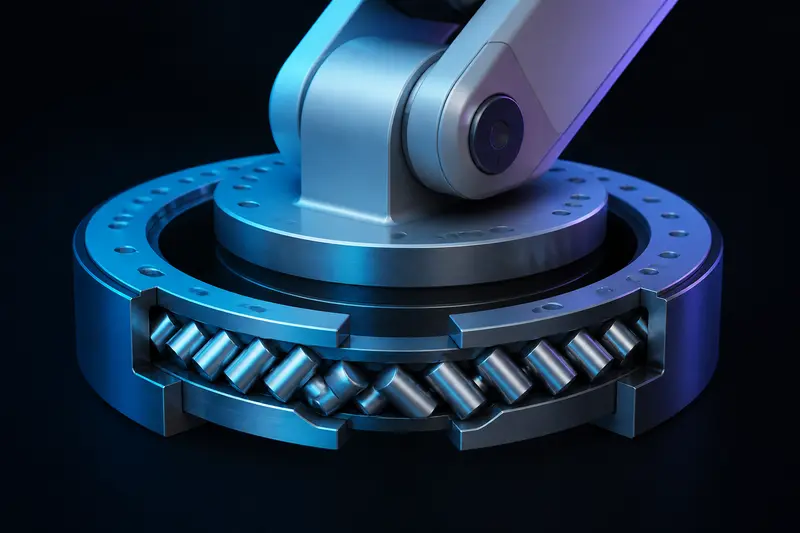
You sized the motor, the gearbox holds the load, the controller is tuned, and the tool tip still wobbles. Push sideways on the end effector of many hobby arms and you can feel a millimeter or two of give that has nothing to do with control gains. Very often the culprit is the joint bearing: either it was chosen for radial load when the real load is a tilting moment, or it is fine on load rating but far too soft in tilt. This article works the actual numbers for one joint, because almost every page on this topic asserts that crossed roller bearings solve the problem without ever computing anything.
Bearing Selection for Robot Arm Joints Starts with the Moment Load
Take the base joint of a desktop 6-DOF arm with a vertical rotation axis. The numbers:
- Payload: 2.0 kg carried at full reach, 500 mm from the joint axis
- Arm structure: 3.0 kg with its center of gravity 250 mm out
- Joint speed is low, so dynamic loads are mild; we will fold them into a safety factor
With the arm stretched out horizontally, gravity produces an overturning moment on the base bearing:
M = 2.0 kg x 9.81 m/s² x 0.50 m + 3.0 kg x 9.81 m/s² x 0.25 m = 9.8 + 7.4 = 17.2 Nm
The same weights press straight down along the axis, giving an axial load Fa = 5.0 kg x 9.81 m/s² = 49 N. Radial load Fr is small for a vertical axis, mostly side forces from acceleration; call it 30 N. Notice the imbalance: the moment term dominates everything. This is the defining feature of bearing selection for robot arm joints. A payload that is trivial as a force becomes a serious load once it acts at the end of a 500 mm lever, and the bearing arrangement has to react that moment across its own small diameter.
Option 1: A Single Crossed Roller Bearing
A crossed roller bearing packs cylindrical rollers alternately tilted 90 degrees to each other in a V-groove raceway, so one thin ring reacts radial, axial, and moment loads at once. Manufacturers give an equivalent load formula of this shape (symbols vary slightly by catalog):
P = X (Fr + 2M / dp) + Y Fa
where dp is the roller pitch diameter. The 2M/dp term is the key move: it converts the moment into an equivalent radial force acting at the roller circle. Take a thin-section crossed roller ring with a 50 mm bore, dp = 65 mm, and a static load rating C0 of 20 kN (representative values; pull the real row from your manufacturer's table). For the static case with X0 = 1 and Y0 = 0.44:
2M / dp = 2 x 17.2 Nm / 0.065 m = 529 N
P0 = 30 N + 529 N + 0.44 x 49 N = 581 N
fs = C0 / P0 = 20000 / 581 = 34
Catalogs ask for a static safety factor fs of about 2 to 3 for smooth motion and 3 to 4 with shocks and vibration. We have 34. That is the first honest conclusion: at hobby arm scale, a crossed roller is nowhere near its load limit. You are not paying for load capacity. You are paying for rigidity, zero play, and the packaging convenience of one flat ring that bolts between two plates.
Option 2: Two Deep Groove Bearings, Spaced Apart
The alternative every builder asks about: put two ordinary deep groove ball bearings on a shaft or tube, separated by a distance L. A bearing pair converts the moment into a force couple:
F = M / L
With two 40 mm bore bearings (6808 size, C0 around 4 kN) spaced L = 40 mm apart:
F = 17.2 Nm / 0.040 m = 430 N radial on each bearing, in opposite directions
Each bearing sees 430 N plus its share of the 49 N axial load, against a 4 kN static rating: a safety factor around 9. Perfectly fine. Now shrink the spacing to 10 mm, which is what happens when you stack two bearings almost touching to save height:
F = 17.2 / 0.010 = 1720 N per bearing
Same joint, same load, four times the bearing force, and the safety factor drops near 2 before any impact factor. Spacing is the free variable in this design: doubling L halves the bearing load and, as we will see, quadruples the tilt stiffness. If the mechanism allows a longer bearing tube, use it.
Two practical notes for the paired arrangement. First, deep groove bearings have internal radial clearance, so an unpreloaded pair will always have a little tilt play; preload the pair axially with a shim or wave spring, or step up to a back-to-back angular contact pair, which spreads the effective load centers even further apart than the physical spacing. Second, do not substitute a stamped lazy susan turntable bearing here. Those have large clearance and flexible races, and they are the single most common source of visible backlash in first-build arm bases.
Stiffness Decides, Not Load Rating
Since both options pass the load check easily, the real comparison is tilt stiffness, because bearing tilt multiplies into tool tip sag by the arm length. Suppose you want no more than 0.1 mm of sag at 500 mm reach from the base bearing alone:
allowed tilt = 0.1 mm / 500 mm = 0.0002 rad (about 0.7 arcmin)
required moment stiffness k = M / tilt = 17.2 Nm / 0.0002 rad = 86 kNm/rad
Small crossed roller rings publish moment rigidity in exactly this range, which is why they show up in harmonic drive output stages. For the bearing pair, each bearing deflects radially by tilt x L/2, so the pair's moment stiffness is approximately:
k = kr x L² / 2
With a preloaded radial stiffness kr of 80 N/µm (8 x 10⁶ N/m, a reasonable order of magnitude for a preloaded ball bearing of this size) and L = 40 mm, k = 8 x 10⁶ x 0.0016 / 2 = 64 kNm/rad, just short of the target. Stretch the spacing to 60 mm and k = 144 kNm/rad, comfortably past it. The L squared scaling is the whole story: a widely spaced pair of cheap bearings can out-stiffen a compact crossed roller, and the crossed roller wins only when the joint must stay axially thin.
A short script to play with your own numbers:
g = 9.81
M = 2.0*g*0.50 + 3.0*g*0.25      # tilting moment, Nm
Fa = 5.0*g                        # axial load, N
Fr = 30.0                         # radial load, N

# crossed roller equivalent static load
dp = 0.065
P0 = (Fr + 2*M/dp) + 0.44*Fa
print("P0 =", round(P0), "N, fs =", round(20000/P0, 1))

# spaced pair: load and tilt stiffness vs spacing
kr = 8e7                          # N/m per bearing, preloaded
for L in (0.010, 0.040, 0.060):
    print(L, "m:", round(M/L), "N per bearing,",
          round(kr*L**2/2/1000), "kNm/rad")
How to Choose in Practice
- Compute the moment first: payload and link weights times their lever arms, at the worst pose. Add a load factor of 1.5 to 2 for accelerations and bumps before comparing against ratings.
- If the joint can be long (a base column, a shoulder tube), use two preloaded bearings spaced as far apart as the structure allows. It is the cheapest stiffness you can buy, and F = M/L tells you exactly what each bearing carries.
- If the joint must be flat (a pancake joint behind a gearbox, a wrist), a crossed roller ring earns its price through moment capacity per millimeter of height. Check P = X(Fr + 2M/dp) + Y Fa against the catalog, but expect stiffness and preload, not load rating, to be the binding constraint.
- Work backwards from tip accuracy: allowed tilt is tip tolerance divided by reach, and required moment stiffness is M divided by that tilt. This one line tells you whether a bearing choice is even in the running.
The bearing does not act alone, of course. The motor and reducer have to hold the same moment through the gear train, which is its own sizing exercise; we walk that calculation in the motor and gearbox torque sizing worked example. And if you end up at a harmonic drive for the reduction, note that many units ship with a crossed roller output bearing already integrated, which can delete this whole problem from your parts list; see the harmonic drive vs planetary gearbox comparison for that tradeoff. Either way, run the moment arithmetic before you buy: it takes five minutes and it is the difference between a joint that feels like a machine tool and one that feels like a shopping cart wheel.
Building or studying robotics?
Arcbotix publishes practical guides on robotics engineering, control systems and real-world builds. Explore more articles on the blog.