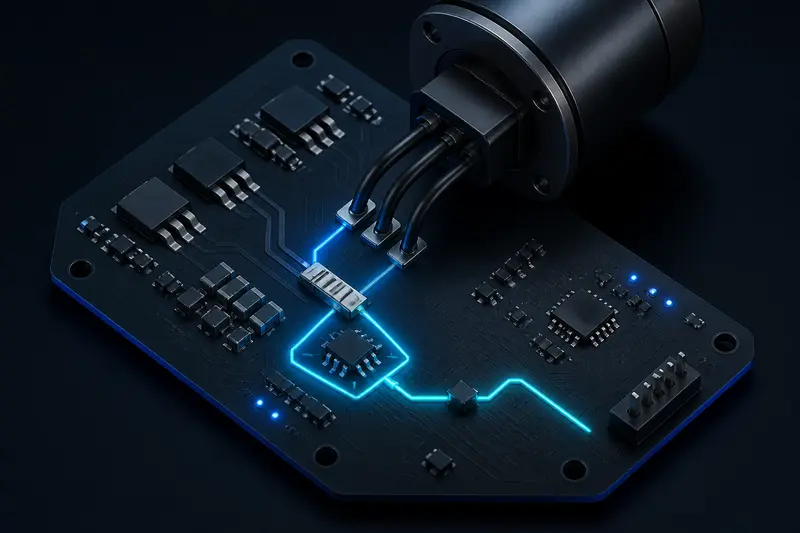
Current sensing circuit design for a robot motor driver comes down to four linked numbers: the shunt resistor value, the power it has to dissipate, the sense-amplifier gain, and the resulting current resolution at the ADC. Most application notes explain each piece in isolation. This article works through all four together for a concrete robot joint driver, so you end with a shunt value and gain you can actually put in a bill of materials.
What the Current-Sense Chain Actually Has to Resolve
Take a joint driver with these requirements, typical of a mid-size arm joint on a 24 V bus:
Continuous current: 8 A
Peak current (short moves, direction changes): 20 A
ADC: 12-bit, 3.3 V reference
The sensing chain has to produce a voltage the microcontroller's ADC can read cleanly across that whole range, without wasting so much power in the shunt that it becomes a heat problem, and without pinning the amplifier output against the supply rail during a peak move.
Step 1: Pick the Shunt Resistor Value
Start from the sense-amplifier's usable input range. A common low-side current-sense amplifier accepts a shunt voltage up to roughly 100 mV before nonlinearity creeps in. Size the shunt so peak current lands at or just under that limit:
Rshunt = Vsense_max / Ipeak = 0.1 V / 20 A = 5 mΩ
5 mΩ is a standard current-sense resistor value, so no custom part is needed. At the two operating points:
Vsense at 20 A peak = 20 × 0.005 = 0.100 V
Vsense at 8 A continuous = 8 × 0.005 = 0.040 V
Step 2: Check the Power Dissipation
Power in the shunt sets the resistor's physical size and package rating:
P_peak = I² × R = 20² × 0.005 = 2.0 W
P_continuous = 8² × 0.005 = 0.32 W
Peak current only lasts for short moves, so the resistor doesn't need to survive 2 W continuously, but it does need enough thermal mass and a low enough thermal resistance to shed that 2 W pulse without a large temperature spike, which would shift its resistance and add measurement error. A 1 W to 2 W surface-mount current-sense resistor with a low temperature coefficient, on a copper pour sized for the continuous 0.32 W, is the usual choice here. Skipping this check is a common way a current-sensing circuit works fine on the bench and then drifts once the joint runs a real duty cycle, similar to how a motor winding itself needs a duty-cycle-based thermal check rather than just a continuous-rating check.
Step 3: Size the Sense-Amplifier Gain
With Rshunt fixed at 5 mΩ, pick an amplifier gain that uses as much of the ADC's input range as possible at peak current without clipping. Using a gain of 20 V/V, a common fixed-gain option in this class of part:
Vout at 20 A peak = 0.100 V × 20 = 2.0 V
Vout at 8 A continuous = 0.040 V × 20 = 0.8 V
Against a 3.3 V ADC reference, 2.0 V at peak current leaves about 1.3 V of headroom, which covers current overshoot during a hard direction reversal without saturating the amplifier output. A higher gain would use more of the ADC range at the cost of that headroom; a lower gain wastes resolution. 20 V/V is a reasonable middle point for this current range.
Step 4: Check the Resulting ADC Resolution
The whole point of the previous three steps is this number: how much current one ADC count actually represents. For a 12-bit ADC on a 3.3 V reference:
1 LSB = 3.3 V / 4096 ≈ 0.8057 mV
Converting that voltage step back through the gain and shunt value gives the current resolution:
Amps per LSB = LSB / (Gain × Rshunt) = 0.0008057 / (20 × 0.005) ≈ 8.06 mA/LSB
For a joint that needs to detect a stall or a light contact event in the tens-of-milliamps range, roughly 8 mA of resolution per count is enough margin. If a design instead needed to resolve single-digit milliamps, the fix is not a finer ADC alone; it's usually a smaller shunt paired with a higher gain, which keeps the same peak-current headroom while shrinking the volts-per-amp step at the low end. It's also worth checking the full-scale current implied by the chain, since that tells you how much margin exists above the expected peak:
Full-scale current = Vref / (Gain × Rshunt) = 3.3 / (20 × 0.005) = 33 A
The 20 A peak sits at about 61 percent of that 33 A full-scale value, which is the same headroom conclusion from the gain step, just expressed as a current instead of a voltage.
Step 5: Low-Side vs High-Side, and Kelvin Sensing
A low-side shunt, placed between the motor driver's low-side switches and ground, is simpler to interface because the amplifier's common-mode voltage stays near ground. Its downside is that it can't distinguish a motor short to ground from a normal high current event, and it sits in the return path shared with other circuitry, which can inject switching noise into other ground-referenced sensors. A high-side shunt, placed between the supply rail and the driver, avoids both problems but needs a sense amplifier rated for the full bus voltage as its common-mode input.
Whichever side you choose, route the sense connections as a proper Kelvin pair: two separate traces from the amplifier straight to the resistor's sense pads, not shared with the traces carrying the load current. A shunt resistor's pads have their own contact resistance, and folding that into the main power path adds an error that swamps the careful gain and resolution numbers above. This is the detail most current-sensing writeups mention in a single sentence and most first-pass PCB layouts get wrong.
Once the shunt, gain, and ADC resolution are sized this way, the resulting current reading feeds directly into a torque-control loop, using the motor's torque constant to convert measured current into commanded torque, or into a stall/collision detection threshold. The sensing hardware and the control loop that consumes it are worth designing as two separate steps: get the volts-per-amp chain right first, then tune the loop that reads it.
Building or studying robotics?
Arcbotix publishes practical guides on robotics engineering, control systems and real-world builds. Explore more articles on the blog.