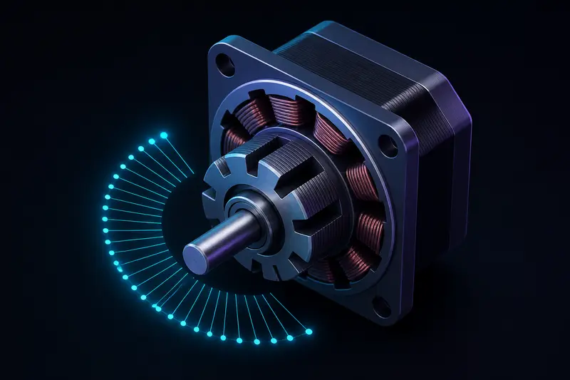
Stepper motor microstepping explained simply: it is a driver technique that positions the rotor between full steps by proportioning current between two motor phases, instead of switching one phase fully on and the other fully off. This guide covers the actual holding-torque-per-microstep formula, how to pick a driver chip for a robot joint, and the missed-step failure mode that catches people who treat microstepping as free resolution.
What Microstepping Actually Changes
A standard hybrid stepper motor has a fixed mechanical step angle, almost always 1.8 degrees (200 full steps per revolution) or 0.9 degrees (400 full steps per revolution). Full-step and half-step drive modes only ever park the rotor at those fixed mechanical positions or the halfway points between them. Microstepping changes this by driving the two phase coils with sine and cosine current waveforms instead of square waves.
At each microstep, the driver sets phase A current to I * cos(theta) and phase B current to I * sin(theta), where theta is the electrical angle for that microstep and I is the configured full-scale current. The resulting magnetic field vector rotates smoothly between the pole positions, and the rotor's detent torque pulls it to follow that vector. A common driver like the A4988 supports up to 16 microsteps per full step (3200 steps/revolution on a 1.8 degree motor), while the DRV8825 supports up to 32, and modern chips like the TMC2209 support up to 256 microsteps per full step in software (51,200 steps/revolution).
The Holding Torque Per Microstep Formula
The torque available to hold the rotor at any given microstep position is:
T(theta) = T_holding * sin(theta)
where T_holding is the motor's rated full-step holding torque and theta is the electrical angle from the nearest full step, in radians. This is the formula that top-ranking industrial motion-control pages state correctly but rarely apply with numbers.
Take a NEMA 17 motor rated at 0.4 N*m (40 N*cm) holding torque, driven at 16 microsteps per full step. The first microstep sits at theta = (1/16) * (pi/2) = 0.0982 rad from the full step. Available torque there is:
T(1) = 0.4 * sin(0.0982) = 0.4 * 0.098 = 0.039 N*m
That is less than 10 percent of the rated holding torque, at the very first microstep. This is why microstepping smooths motion and improves positioning resolution, but does not raise the torque the motor can actually push against while stationary between full steps. If your robot joint needs to hold a load against gravity between full-step positions, size the motor for that reduced torque, not the datasheet holding-torque number.
Resolution vs Real Accuracy
Microstepping resolution is not the same as mechanical accuracy. Rotor detent positions are set by the physical pole geometry, and microstep positions between them depend on the linearity of the driver's current control and the motor's own magnetic nonlinearity. In practice, a 1.8 degree stepper with 16x microstepping will have real positional error of a few percent of a full step at each individual microstep, even though the commanded resolution is 0.1125 degrees. For a robot arm joint after a gear reduction, this error shrinks proportionally, which is one reason microstepping matters more for direct-drive or lightly geared joints than for heavily reduced ones already covered by harmonic drive and planetary gearbox choices.
Choosing a Microstepping Resolution for a Robot Build
- 1/8 to 1/16 microstepping: good default for hobby robot arms and small mobile bases. Noticeably smoother and quieter than full-step, without pushing the driver's current-control bandwidth or CPU step-pulse rate too hard.
- 1/32 to 1/256 microstepping: useful for very smooth, low-vibration motion (camera gimbals, precision linear stages) or for driver chips like the TMC2209 that do sine-wave interpolation internally (marketed as StealthChop or similar) regardless of the step resolution your controller commands.
- Full or half step: still the right choice when you need maximum torque per step and can tolerate more vibration, for example a low-speed, high-load lead screw axis.
Step pulse rate is the practical limit on how much microstepping you can use. Commanding the same shaft speed at 256 microsteps instead of full steps means issuing 256 times as many step pulses per second. A microcontroller bit-banging step pulses in a tight loop, or a Raspberry Pi generating pulses in software, will run out of headroom well before a dedicated motion controller does. Check your controller's maximum sustainable step rate before assuming a high microstepping setting is free.
How Missed Steps Actually Happen
A stepper motor is an open-loop position device unless you add an encoder. It commits to a commanded position by assuming the rotor tracked every microstep. Two failure modes break that assumption:
- Torque saturation: if the load torque at any point in the motion exceeds the available torque at that microstep angle (recall T(theta) drops to near zero right after each full step), the rotor slips backward relative to the commanded field position. The driver has no idea this happened, because it never reads rotor position.
- Resonance: stepper motors have a natural mechanical resonance frequency, often in the 100-300 Hz full-step-rate range for small NEMA motors. Driving near that frequency, especially at low microstepping settings, can cause the rotor to lose synchronization even under light load. Higher microstepping settings smooth the torque ripple that excites this resonance, which is a second, distinct reason to use microstepping beyond visual smoothness.
A missed step is silent and cumulative: the controller's internal position count and the rotor's actual position permanently diverge by one or more full steps, and every subsequent move is offset by that error. This is the practical argument for adding a quadrature encoder to a stepper-driven joint on anything beyond a low-stakes hobby project, using the same quadrature encoder wiring and CPR-to-angle conversion approach used for other feedback-driven joints, and periodically re-homing against a limit switch or index pulse to catch any accumulated drift.
Practical Driver Chip Notes
- A4988: fixed microstep resolutions up to 1/16, simple to wire, common on cheap hobby boards, but has no stall detection and gets hot at higher currents without a heatsink and fan.
- DRV8825: up to 1/32 microstepping, higher current rating than the A4988, still purely open-loop with no back-EMF sensing.
- TMC2209 and similar Trinamic chips: up to 1/256 microstepping with internal interpolation, plus StallGuard-style back-EMF sensing that can detect (not prevent) a stall condition, which is genuinely useful for adding a software-level missed-step check without a physical encoder.
Conclusion
Microstepping smooths motion, reduces resonance-driven step loss, and increases commanded positional resolution, but it does not increase available torque between full steps, and it does not turn an open-loop stepper into a closed-loop system. Size your motor for the reduced torque at the worst-case microstep angle, pick a microstepping resolution your controller can actually sustain at your target speed, and if the joint carries real load or needs guaranteed position, add encoder feedback rather than trusting step count alone.
Building or studying robotics?
Arcbotix publishes practical guides on robotics engineering, control systems and real-world builds. Explore more articles on the blog.